A
B
C
D
E
F
G
H
L
M
N
P
Impianto elettrico
Electric system
sezione / section
P 1
7ST3 - M.Y. 2004 - edizione/edition 00
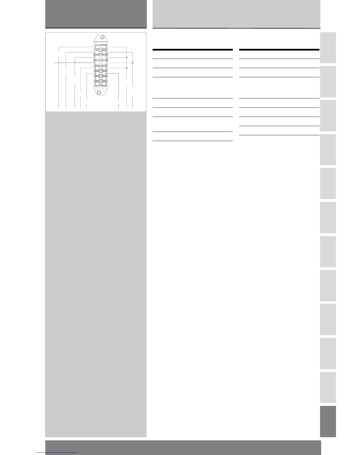
Legenda scatola fusibili
impianto elettrico
Per il controllo dei fusibili (Sez. P 6).
Disposizione dei cablaggi
sul motociclo
Tutti i percorsi dei cablaggi dell’im-
pianto elettrico sono stati ottimizzati
per avere il minimo ingombro.
Ogni passaggio è stato studiato per
non interferire durante l’utilizzo della
moto con organi che potrebbero dan-
neggiarli o procurare anomalie di fun-
zionamento. Le tavole che riportiamo
di seguito evidenziano i punti di origi-
ne (punti “0”) per il riposizionamento
corretto dei cavi e i punti di posiziona-
mento delle fascette stringitubo.
In ogni figura sono indicati i rimandi
alle tavole nelle quali il riparatore potrà
seguire il proseguimento del cavo in-
teressato oppure l’utilizzatore a cui va
collegato.
Pos. Utilizzatore
Val
.
1-9 Key-on 7,5 A
2-10 Luci 15 A
3-11 Clacson, stop,
teleruttore, indicatori
di direzione
20 A
4-12 NQS 5 A
5-13 Manopole riscaldate 5 A
6-14 Interruttore stampella
laterale
3 A
7-15 Riserva 15 A
8-16 Riserva 20 A
Electrical system fuse
box legend
See Section P 6 for information on
checking fuses.
Arrangement of wiring on
frame
Routing of wiring has been optimized
to ensure the minimum obstruction.
Each section is designed to prevent
interference with parts that might
damage wires or cause operating
failures when riding. The diagrams on
the following pages show the origins
("0" points) for cables proper re-
routing and cable ties locations.
Each figure includes references to the
diagrams showing the cable routing
or the item it will have to be connect-
ed to.
Pos. Circuit
Val
ue
1-9 Ignition key switch 7,5 A
2-10 Lights 15 A
3-11 Horn, stop lights,
starter switch, turn
indicators
20 A
4-12 NQS 5 A
5-13 Heated hand grips 5 A
6-14 Side stand switch 3 A
7-15 Spare 15 A
8-16 Spare 20 A
O
R/Bk
R/B
Bn/Y
R
R/W
Bk/Gr Bk/Gr
1
2
3
4
5
6
7
8
9
10
11
12
13
14
15
16