A
B
C
D
E
F
G
H
L
M
N
P
Impianto elettrico
Electric system
sezione / section
P 3
40 ST3 - M.Y. 2004 - edizione/edition 00
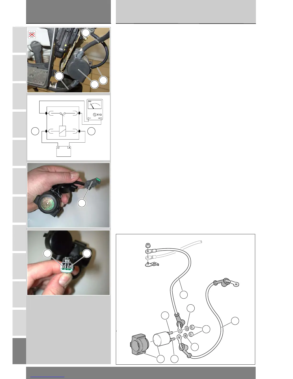
Contactor
The starter motor relay (1) is mounted
on a bracket secured to the horizontal
cylinder head. The regulator-rectifier
fuse is located on the same bracket
Disconnect the battery (Sect. P 2).
Remove the starter contactor from
the battery mount.
Undo the nuts (4) and collect the
spring washers (3).
Remove the contactor-starter motor
cable (2). Remove the contactor-
battery cable (5).
Disconnect the connector (6) of the
starter contactor from the wiring.
Starter contactor operational
check
Apply a 12V (battery) across the
positive (A) and negative (B) terminals
of the connector.
Connect a multimeter between the
two poles [threaded pins (C) and (D)]
of the starter contactor and then
check for electric continuity
(Sect. P 9). If continuity is not
ensured, replace the starter
contactor.
At reassembly, check that contacts
(C) and (D) are not oxidized and use
waterproof spray.
Tighten the nuts (4) to the specified
torque (Sect. C 3).
Reconnect connector (2) to wiring.
Fit the starter motor relay to the
mounting bracket. Push the relay all
the way on to the bracket until the
four prongs of the bracket protrude
from the side of the relay.
Teleruttore
Il teleruttore avviamento (1) è
posizionato su una staffa che è fissata
alla testa orizzontale: sulla stessa staffa
è posizionato anche il fusibile
regolatore.
Scollegare la batteria (Sez. P 2).
Rimuovere il teleruttore avviamento dal
proprio alloggiamento nel supporto
batteria.
Svitare i dadi (4) facendo attenzione alle
rosette elastiche (3).
Rimuovere il cavo (2) teleruttore-
motorino avviamento. Rimuovere il
cavo (5) teleruttore-batteria.
Scollegare il connettore (6) del
teleruttore avviamento dal cablaggio.
Controllo funzionalità teleruttore
avviamento
Applicare una tensione di 12V (batteria)
ai due terminali (A) Positivo e (B)
Negativo del connettore.
Con un multimetro collegato fra i due
poli (perni filettati) (C) e (D) del
teleruttore verificare la presenza della
continuità elettrica (Sez. P 9). Se non è
presente continuità elettrica, sostituire
il teleruttore.
Durante il rimontaggio, verificare che i
poli (C) e (D) non siano ossidati e
applicare spray idrorepellente.
Serrare i dadi (4) alla coppia prescritta
(Sez. C 3). Rimontare il connettore (6) al
cablaggio. Inserire il teleruttore nella
staffa di supporto: il teleruttore deve
essere inserito completamente, ossia
fino a far uscire sul lato del teleruttore
stesso i quattro denti di fermo della
staffa di supporto.
1
D
C
5
3
3
4
2
6
5
1
2
12V
B A
6
+ -