A
B
C
D
E
F
G
H
L
M
N
P
Impianto elettrico
Electric system
sezione / section
P 4
44 ST3 - M.Y. 2004 - edizione/edition 00
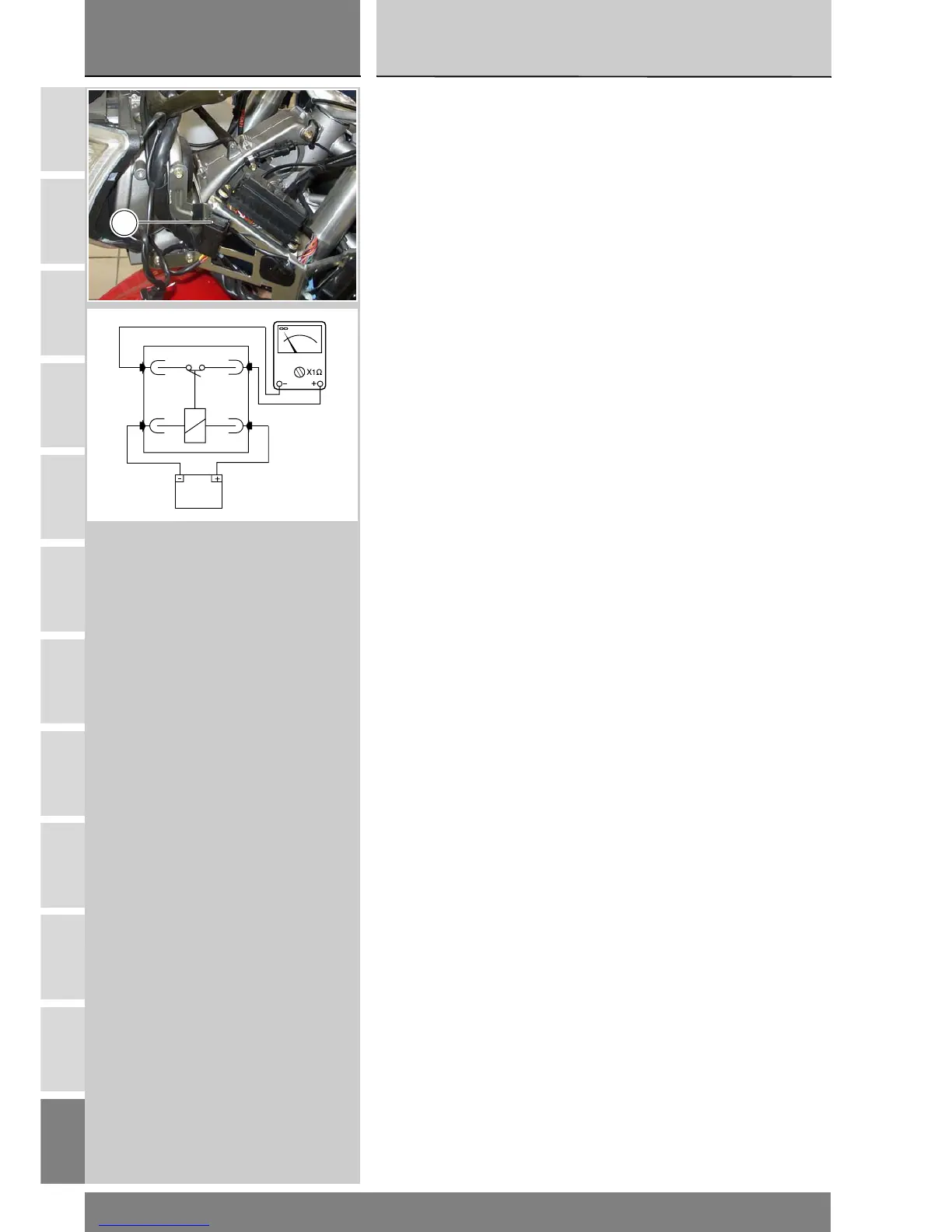
Relè luci abbaglianti
E' posizionato sul lato sinistro
anteriore.
Per avere accesso a questo
componente è necessario rimuovere
il cupolino (Sez. E 1).
Il relè luci abbaglianti (1) è stato
introdotto nell'impianto per poter
eseguire la strategia di spegnimento
luci che consiste:
1 Le luci se accese si spengono
simultaneamente all'atto
dell'avviamento veicolo.
2 Le luci se accese si spengono se
dopo 60 secondi da chiave ON con
motore spento.
In caso di non funzionamento di
questa strategia verificare il corretto
funzionamento.
Controllo funzionalità relè luci
abbaglianti
Scollegare il relè dall'impianto
elettrico e applicare una tensione di
12V (batteria) tra i contatti piccoli: si
deve sentire uno scatto che indica il
funzionamento dell'elettrocalamita
interna.
Collegare un multimetro ai contatti
grandi per verificare la continuità
elettrica (Sez. P 9). La resistenza
indicata dallo strumento deve essere
prossima allo zero e, se presente,
deve essere emesso il segnale
sonoro di continuità. Se ciò non si
verifica sostituire l'elemento.
Headlight switching relay
The headlight switching relay is
located on the front left frame
section.
To access the relay, remove the
headlight fairing (Section E 1).
The headlight switching relay (1)
enables energy saving switching logic
to be implemented. This logic works
as follows:
1 If the lights are on, they are
switched off while the engine is being
started.
2 If the lights are on, they are
switched off 60 seconds after the
ignition key is turned ON if the engine
is not started.
If the headlights do not work in this
way, check the functioning of the
relay.
Checking headlight relay
functioning
Disconnect the relay from the
electrical system and apply a voltage
of 12 V (from the battery) across its
small contacts. If the relay is working
correctly you will hear the solenoid
inside it clicking.
Connect a multi-meter across the
large contacts and check that the
circuit is continuous (Section P 9).
The multi-meter must read out a
resistance of virtually zero, and multi-
meters with beepers must beep to
confirm electrical continuity. If this is
not the case, replace the relay.
1
12V