A
B
C
D
E
F
G
H
L
M
N
P
Impianto elettrico
Electric system
sezione / section
P 6
54 ST3 - M.Y. 2004 - edizione/edition 00
6 - DISPOSITIVI DI
SICUREZZA
E PROTEZIONE
Controllo componenti
Controllo commutatore a
chiave
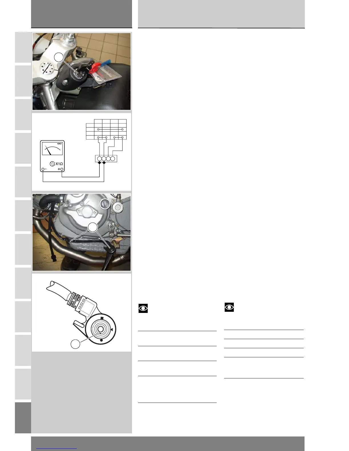
Scollegare il commutatore a chiave
(A) dall'impianto elettrico aprendo la
sua connessione (Sez. P 1) e
verificare con un multimetro (Sez. P 9)
la continuità dei collegamenti interni
operando come segue:
girare la chiave sulla posizione ON e
collegare un multimetro ai contatti (3)
e (6) e poi a quelli (2) e (5) per
verificare la continuità elettrica
(Sez. P 9, relativa al funzionamento
del multimetro). La resistenza
indicata dallo strumento deve essere
prossima allo zero e, se presente,
deve essere emesso il segnale
sonoro di continuità;
portare la chiave su PARK e collegare
un multimetro ai contatti (3) e (5) per
verificare la continuità elettrica.
La resistenza indicata dallo strumento
deve essere prossima allo zero e,
se presente, deve essere emesso il
segnale sonoro di continuità.
Controllo interruttore stampel-
la laterale
Rimuovere l’interruttore (1) dalla
stampella (Sez. H 5) e scollegare la
connessione del cablaggio principale
dall’interruttore stesso (vedi capitolo
“Disposizione dei cablaggi sul
motociclo” Sez. P1).
Con il multimetro (Sez. P 9) verificare
il funzionamento dell’interruttore
(vedi tabella).
Note
La medesima verifica può
essere eseguita con lo strumento di
diagnosi “Mathesis” (Sez. D 5).
❍ = Contatto aperto
X = Contatto chiuso
Pos. piolo
(A)
Utilizzatori Val.
● - ▲❍ X
▲ - ■ X ❍
Pos. multi-
metro
Verde/
Verde
Bianco
Verde/
Giallo
Nero
6 - PROTECTION AND
SAFETY DEVICES
Checking components
Checking the ignition key
switch
Disconnect the ignition key switch (A)
from the electrical system by undoing
the relevant connection (Section P 1)
and use a multi-meter (see
Section P 9) to check the internal
connections for electrical
continuity as follows:
Turn the ignition switch to the ON
position and connect a multi-meter
across the contacts (3) and (6) and
then across contacts (2) and (5) to
check for electrical continuity (see
Section P 9 for use of the multi-
meter). The multi-meter must read
out a resistance of virtually zero, and
multi-meters with beepers must
beep to confirm electrical continuity.
Now turn the key to the PARK
position and connect the multi-meter
across contacts (3) and (5) to check
for electrical continuity. The multi-
meter must read out a resistance of
virtually zero, and multi-meters with
beepers must beep to confirm
electrical continuity.
Side stand switch
Remove the switch (1) from the side
stand (see Section H 5) and
disconnect the wiring harness
connector from the switch (refer to
"Cable routing on the motorcycle" in
Section P 1).
Use the multi-meter (see Section P 9)
to check the switch for correct
functioning (see the table below).
Note
This check can also be
performed using the "Mathesis"
diagnostic tester (see Section D 5).
0 = Open contact
X = Closed contact
Pin Pos. (A) El. items Val.
● - ▲ 0X
▲ - ■ X0
Multimeter
pos.
Green/
Green
White
Green/
Yellow
Black
A
LOCK
PARK
OFF
ON
R G/Bk G/R Y
53
6
2
1
A
P