A
B
C
D
E
F
G
H
L
M
N
P
Mototelaio
Frame
sezione / section
H 2
10 ST3 - M.Y. 2004 - edizione/edition 00
Smontaggio componenti
cannotto di sterzo
Note
Tutti i componenti che sono fis-
sati sulla testa e sulla base di sterzo,
compreso i cavi elettrici e le trasmis-
sioni flessibili, possono rimanere
montati a condizione che non vadano
ad interferire con le operazioni da es-
eguire.
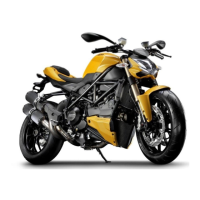
Allentare la vite (1) di bloccaggio del
perno sulla testa di sterzo (2).
Con l’ausilio di un martello di gomma
sfilare la testa di sterzo (2) dalla ghiera
(3) e dagli steli forcella.
Con l’attrezzo cod. 88713.1058 allen-
tare la ghiera (3) e svitarla dal perno di
sterzo.
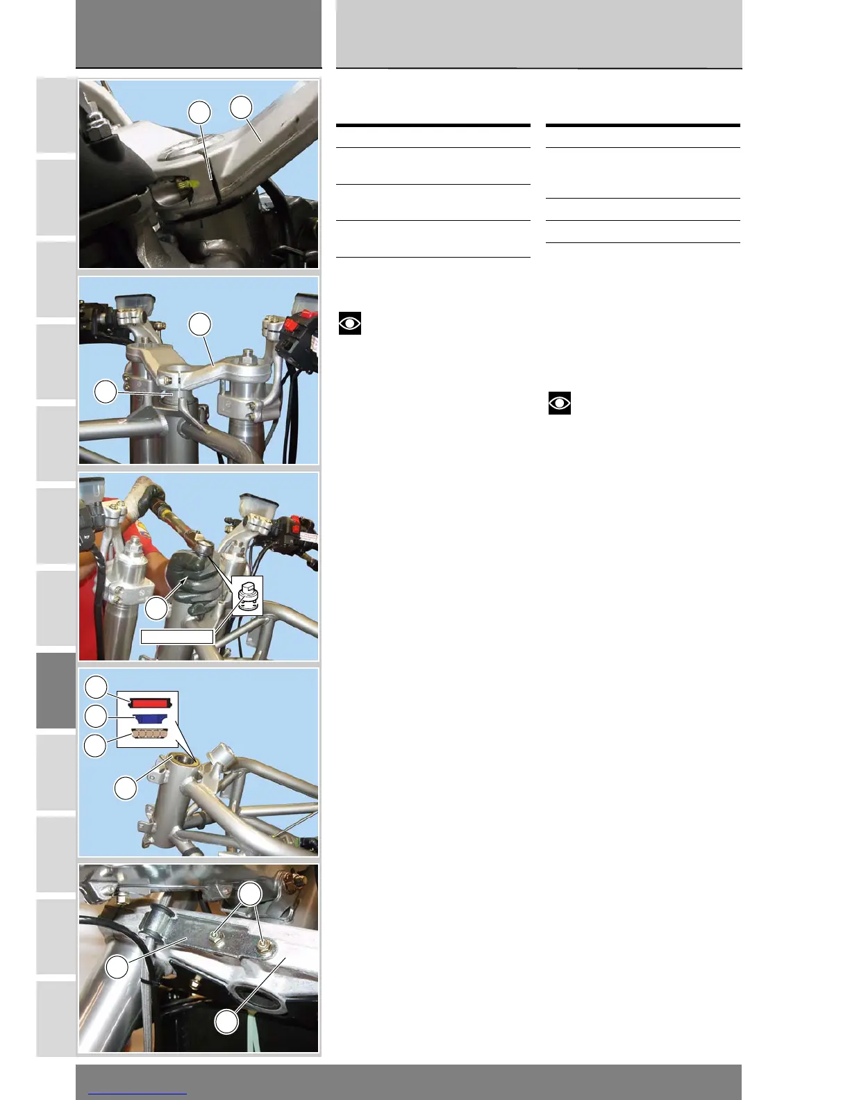
Sfilare dal tubo del telaio l’anello di te-
nuta (4), l’anello interno (A) e la corona
di sfere (B) del cuscinetto (5) superi-
ore.
Scollegare il tubo freno anteriore fis-
sato alla base di sterzo (9) dal suppor-
to (C) svitando le viti (D).
Operazioni Rif. Sez.
Rimuovere specchietti,
cupolino e plance
E 1
Rimuovere la ruota
anteriore
G 1
Rimuovere gli steli
forcella
G 2
Rimuovere i supporti
semimanubri
H 1
Removing the steering
head bearings
Steering shaft is supported by two
ball bearings (5) and (6) with outer oil
seals (4) and (7) on the frame tube.
Ring nut (3), which is positioned on
steering shaft, defines steering
bearing clearance.
Note
All the parts fitted to steering
head and bottom yoke, wires and
Bowden cables included, can be left
on vehicle in case they do not hinder
the following operations.
Loosen retaining screw (1) holding
steering shaft to steering head (2).
Using a rubber mallet, remove
steering head (2) from ring nut (3) and
fork legs.
Using tool part no. 88713.1058
loosen ring nut (3) and remove it from
steering shaft.
Remove oil seal (4), inner ring (A) and
ball ring (B) of upper bearing (5) from
frame tube.
Operations See Sect.
Remove the rear view
mirrors, headlight
fairing and dash panels
E 1
Remove front wheel G 1
Remove the fork legs G 2
Remove the handlebar
mountings
H 1
2
1
2
3
88713.1058
3
4
A
B
4
C
D
9