A
B
C
D
E
F
G
H
L
M
N
P
Ruote - Sospensioni - Freni
Wheels - Suspensions - Brakes
sezione / section
G 7
37ST3 - M.Y. 2004 - edizione/edition 00
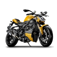
Sistema sospensione
posteriore
La sospensione posteriore utilizza un
monoammortizzatore oleopneumatico
(6) completamente regolabile con
azionamento progressivo.
Questo sistema è composto da un
bilanciere superiore (1) e da un tirante
non regolabile (16) fissato
inferiormente al forcellone. Il
forcellone, in acciaio, è infulcrato sul
motore per ottenere la massima
rigidità.
Per le regolazioni dell’ammortizzatore
posteriore fare riferimento alla Sez. D
4.
Smontaggio
ammortizzatore
posteriore
Svitare la vite (11) di fissaggio al
forcellone posta sul lato destro.
Rimuovendo la vite (11) si libera
anche il tirante (16) dal forcellone
abbassare il forcellone e recuperare la
bussola filettata (12), il rasamento (14)
e le bussole (4) poste ai lati dello
snodo sferico (13) del tirante.
Svitare la vite (5) di fissaggio
ammortizzatore al bilancere superiore
(1).
Rimuovere l’ammortizzatore (6)
completo dal veicolo.
Operazioni Rif. Sez.
Rimuovere il codone
posteriore
E 3
Rimuovere la ruota
posteriore
G 4
Rimuovere la pedana
pilota destra
H 4
Rear suspension unit
The rear suspension consists of a
fully adjustable progressive hydraulic
monoshock (6).
This system consists of an upper
rocker arm (1) and an adjustable
linkage (16) which is fixed to the
swingarm at the bottom. The steel
swingarm is fixed to frame for
maximum stiffness.
See Section D 4 for rear shock
absorber adjustment procedures.
Removing the rear shock
absorber
Unscrew the bolt (11) securing the
shock absorber to the swingarm from
the RH side.
When you remove the bolt (11) the
link rod (16) is also released from the
swingarm. Lower the swingarm and
remove the threaded bush (12),
spacer (14) and bushes (4) from either
side of the link rod bearing (13).
Loosen retaining screw (5) from
upper rocker arm (1).
Remove the complete shock
absorber (6) from vehicle.
Operations See Sect.
Remove tail guard E 3
Remove rear wheel G 4
Remove the RH rider
footpeg
H 4
11
11
4
12
14
13
16
4
1
6
5