A
B
C
D
E
F
G
H
L
M
N
P
Motore
Engine
sezione / section
N 3.1
31ST3 - M.Y. 2004 - edizione/edition 00
Impianto di
raffreddamento
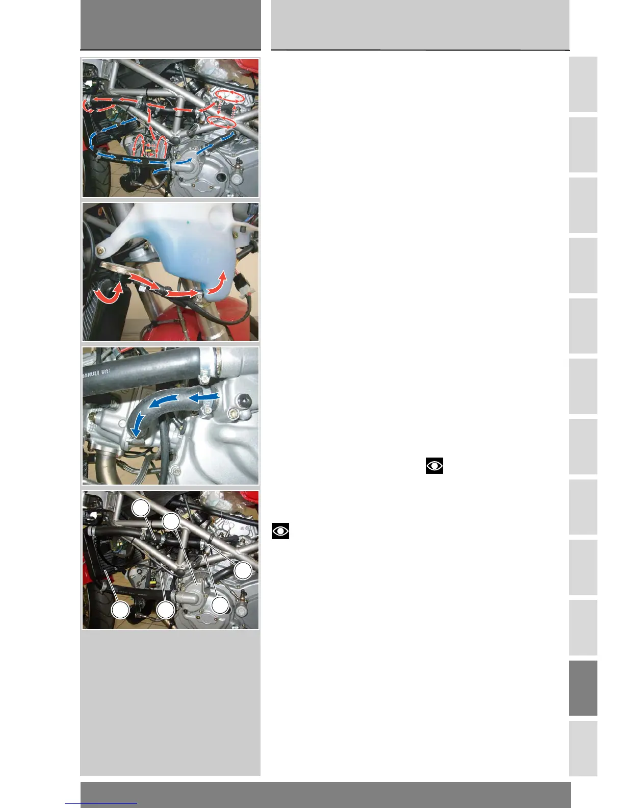
Descrizione circuito impianto
di raffreddamento
Circuito pressurizzato con radiatore
curvo dotato di elettroventola e
termostato a miscelazione. Una
pompa centrifuga, comandata
dall’albero di distribuzione, mette in
circolazione il liquido e un serbatoio di
espansione recupera le dilatazioni
termiche del refrigerante.
Capacità circuito: 2,5 It
Il liquido viene spinto dalla pompa
centrifuga ad entrambe le teste, entra
nelle canalizzazioni e successivamente
esce dal raccordo (1) posizionato sulla
testa orizzontale e dal raccordo (2)
posizionato sulla testa verticale.
A congiunzione delle tubazioni di
uscita liquido è posizionato un
termostato (5) che regola l'afflusso
del liquido al radiatore in base agli
impulsi inviati dal sensore
temperatura (3).
Fino ad una temperatura inferiore ai
65/84° F l'afflusso del liquido al
radiatore (6) è minimo ma tale da
garantire la sua circolazione all'interno
del circuito.
Quando la temperatura supera i 65/
84° F il termostato (5) si apre in modo
da permettere il massimo afflusso di
liquido al radiatore (6) e quindi
garantire una diminuzione della
temperatura.
Inserzione elettroventola radiatore (6)
103°, diserzione elettroventola
a 102°.
Note
I dati di pressione massima
raggiungibile prima dell'apertura del
tappo, inizio apertura termostato,
inserzione e diserzione elettroventola
sono riportati (Sez. C 1.1).
Legenda componenti impianto
di raffreddamento
1 Raccordo uscita testa orizzontale
2 Raccordo uscita testa verticale
3 Sensore temperatura
4 Pompa centrifuga
5 Termostato
6 Radiatore acqua
Cooling system
Description of the cooling
system
Pressurized cooling circuit with
curved radiator, electric fan and
mixing thermostat.
Coolant is circulated by a centrifugal
pump driven by the camshaft and an
expansion reservoir recovers coolant
expansion when hot.
Circuit total capacity: 2.5 l
Coolant is fed by the centrifugal pump
to both cylinder heads, where it
passes through the cooling ducts
before leaving through the union (1)
on the horizontal head and union (2)
on the vertical head. A thermostat (5)
is located at the join in the return lines
to regulate oil flow to the radiator
according to signals from the engine
temperature sensor (3).
While coolant temperature remains
below 65/84° F, flow to the radiator
(6) is reduced but still sufficient to
ensure circulation through the
system.
When temperature exceeds 65/
84° F, the thermostat (5) opens to
permit a full flow of coolant to the
radiator (6), thus preventing engine
temperature from rising further.
The fan of the radiator (6) comes on at
103° and goes off at 102°.
Note
The data relating to max.
allowed pressure before plug
opening, thermostat opening value
and electric fan switching on and off
values can be found in (Sect. C 1.1).
Cooling system legend
1 Horizontal head return union
2 Vertical head return union
3 Coolant temperature sensor
4 Centrifugal pump
5 Thermostat
6Radiator
6
5
4
1
2
3