A
B
C
D
E
F
G
H
L
M
N
P
Ruote - Sospensioni - Freni
Wheels - Suspensions - Brakes
sezione / section
G 4
27ST3 - M.Y. 2004 - edizione/edition 00
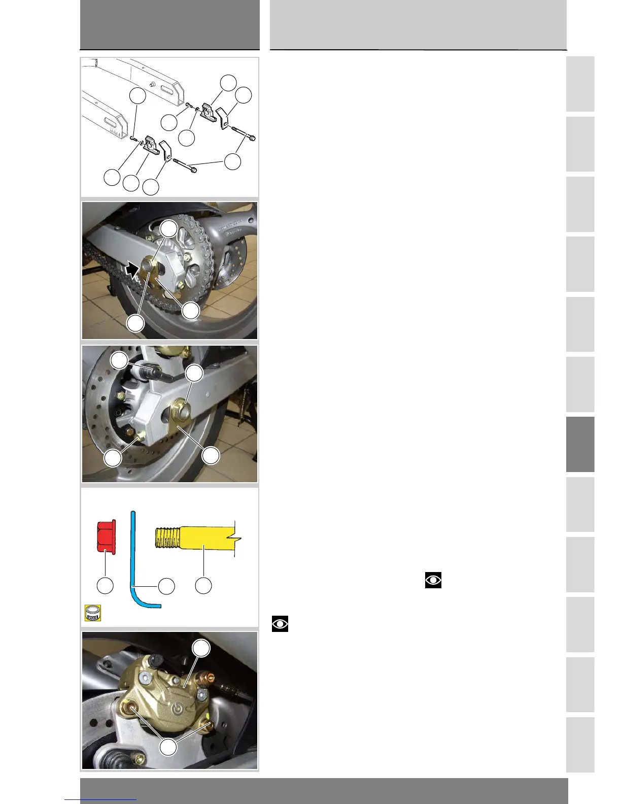
Rimontaggio ruota
posteriore
Inserire la flangia porta corona nella
ruota (Sez. G 8).
Se il cursore (3) è stato rimosso, in-
serirlo nel forcellone, insieme al co-
perchio (5) e impuntare le viti (6).
Inserire il primo piastrino (2) nel perno
(4).
Applicare grasso sul filetto del perno
(4).
Inserire il perno ruota dal lato destro
del forcellone, facendo attenzione a
centrare il foro del cursore tendicate-
na destro.
Tenere in posizione la piastra porta
pinza nel fermo del forcellone, inser-
endo il fermo nell’asola della piastra
stessa.
Introdurre la ruota nel forcellone.
Spingere il perno (4) ruota fino a bat-
tuta, dal lato destro del forcellone, in-
serendolo nel mozzo ruota, nel foro
della piastra porta pinza e nel foro del
cursore tendicatena sinistro.
Fare attenzione a posizionare il piede
del piastrino (2) nella parte inferiore
del forcellone.
Inserire la catena sulla corona.
Inserire il secondo piastrino (2) sul
lato sinistro del forcellone.
Applicare grasso sul piano di giunzi-
one del dado (1) e impuntarlo sul per-
no (4).
Portare il dado fino a battuta, avvitan-
dolo a mano.
Eseguire le operazioni di tensione cat-
ena e di allineamento ruota (Sez. D 4).
Verificare che il tubo freno non risulti
schiacciato o eccessivamente piega-
to.
Serrare il dado (1) sul perno (4) ruota
alla coppia prescritta (Sez. C 3).
Serrare le viti (6) dei tendicatena alla
coppia prescritta (Sez. C 3).
Rimontare la pinza freno (A), serrando
le viti (B) alla coppia prescritta (Sez. C
3).
Note
Il traferro fra sensore (F) e vite
di fissaggio disco freno deve essere
compreso tra 0,6÷2,2 mm
Refitting the rear wheel
Fit the sprocket flange to the wheel
(Section G 8).
If removed, fit the slider (3) into the
swingarm along with the cover (5)
and then fit the screws (6).
Fit the first plate (2) into the shaft (4).
Grease the shaft thread (4).
Fit the wheel shaft from swingarm
left side. Ensure that the left chain
tightener slider hole is duly centered.
Keep the caliper plate into the
swingarm retainer and fit the retainer
into the plate slot.
Fit the wheel into the swingarm.
Push the wheel shaft (4) fully home
from the left side of the swingarm; it
should pass into wheel hub, brake
caliper plate hole and the r.h. chain
slider hole.
Ensure that the plate foot (2) is
positioned at swingarm bottom.
Fit the chain onto the sprocket.
Fit the second plate (2) onto
swingarm right side.
Apply the specified grease to nut
connection surface (1) and fit onto the
shaft (4).
Tighten the nut fully home by hand.
Tighten the chain and align the wheel
(Sect. D 4).
Ensure that the brake hose is not
squashed or excessively bent.
Tighten the nut (1) on the wheel shaft
(2) to the specified torque (Sect. C 3).
Tighten the nut (1) on the wheel shaft
(4) to the specified torque (Sect. C 3).
Tighten the chain tension adjuster
screws (6) to the specified torque
(Section C 3).
Refit the brake calliper (A) and tighten
the retaining screws (B) to the
specified torque (Section C 3).
Note
The air gap between sensor (C)
and brake disc retaining screw should
be included between 0.6 and 2.2
mm.
12
11
3
5
6
5
3
12
11
2
1
4
1
F
6
2
B
1
2
4
B
A