A
B
C
D
E
F
G
H
L
M
N
P
Ruote - Sospensioni - Freni
Wheels - Suspensions - Brakes
sezione / section
G 6
35ST3 - M.Y. 2004 - edizione/edition 00
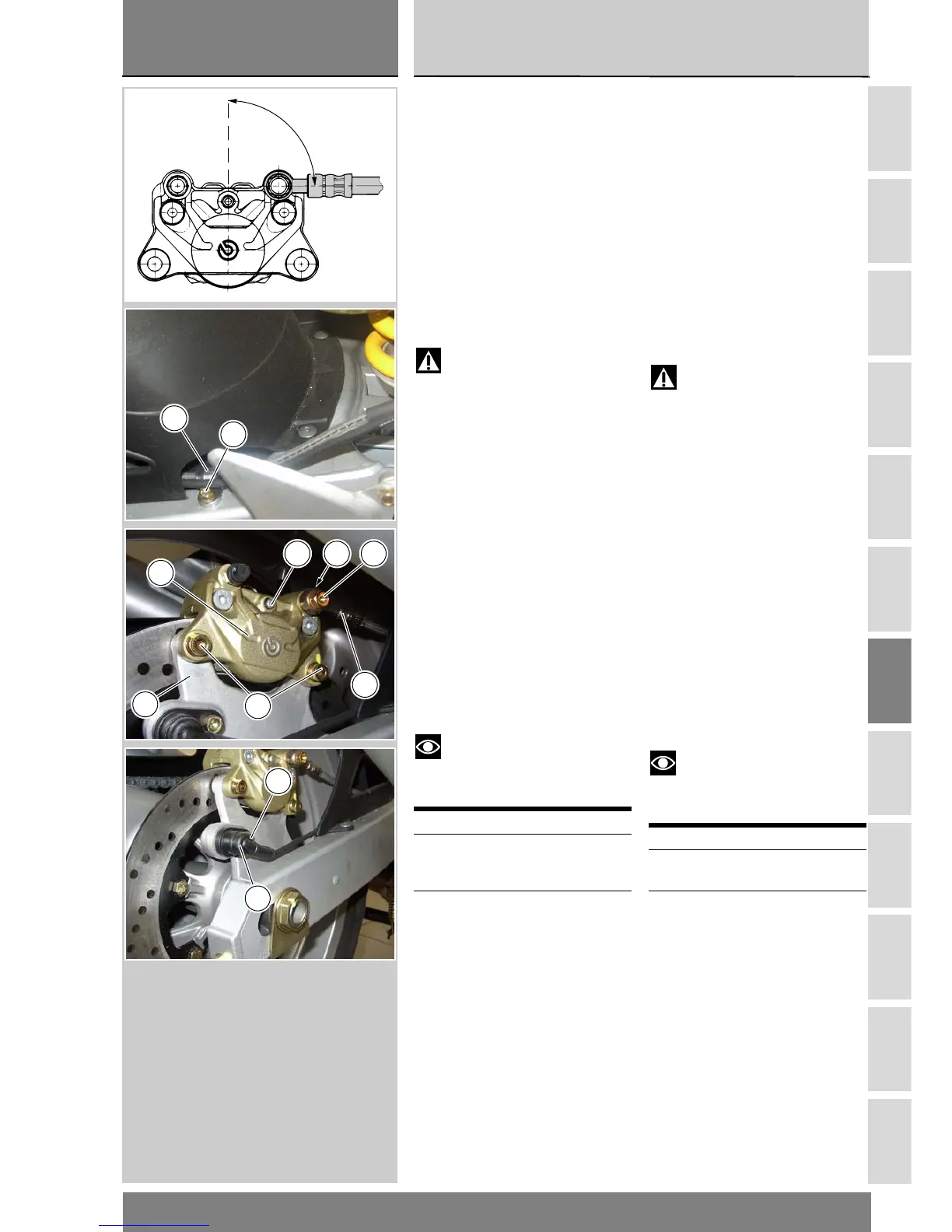
Rimontaggio impianto
freno posteriore
Se è stato rimosso il sensore velocità
(6), posizionarlo sulla piastra porta pin-
za con il distanziale (7) e serrare la vite
(5) alla coppia prescritta (Sez. C 3).
Il fissaggio del tubo freno (A) sulla pin-
za deve essere eseguito interponen-
do sul raccordo le apposite guarnizioni
in rame (2).
Orientare i raccordi del tubo (A) sulla
pinza come indicato in figura.
Attenzione
Una tubazione mal posizionata
può causare un malfunzionamento
dell’impianto frenante e può ostaco-
lare le parti in movimento del motoci-
clo.
Serrare le viti speciali (1) alla coppia
prescritta (Sez. C 3).
Posizionare il tubo freno (A) sul forcel-
lone e fissare la graffetta (14) con la
vite (13).
Inserire la pinza freno posteriore (3)
sul disco freno e allinearla ai fori della
piastra portapinza (8).
Applicare grasso su filetto e sottotes-
ta delle viti (4).
Inserire le rosette (2) sulle viti (4).
Serrare le viti (4) alla coppia prescritta
(Sez. C 3).
Note
Il traferro del sensore (6) e vite
(5) di fissaggio disco freno deve es-
sere compreso tra 0,6÷2,2 mm
Operazioni Rif. Sez.
Serrare la vite di fissag-
gio tubazione alla
pompa freno posteriore
F 4
Riempimento
dell’impianto frenante
D 4
Refitting the rear brake
system
If the speed sensor (6) has been
removed, fit it to the caliper mounting
pate with spacer (7) and tighten the
bolt (5) to the specified torque (see
Section C 3).
Fit the union of the brake hose (A) to
the caliper with the copper seals (2)
on either side of it.
Position the union of the brake hose
(A) at the angle shown in the figure.
Warning
Incorrect hose positioning can
cause brake malfunctioning and
interfere with moving parts.
Tighten the union bolt (1) to the
specified torque (see Section C 3).
Secure the bake hose (A) to the
swingarm with the hose clamp (14)
and screw (13).
Fit the rear brake caliper (3) over the
brake disc and align it with the holes
in the caliper mounting plate (8).
Smear some grease on the threads
and underside of the retaining bolts
(4).
Fit the washers behind the retaining
bolts (4).
Tighten the retaining bolts (4) to the
specified torque (see Section C 3).
Note
The gap between the speed
sensor (6) and the disc retaining bolts
must be 0.6-2.2 mm.
Operations See Sect.
Fix the hose to the
brake master cylinder
F 4
Fill the braking circuit
with fluid
D 4
90 –2
14
13
4
3
11 12
8
A
6
5