A
B
C
D
E
F
G
H
L
M
N
P
Motore
Engine
sezione / section
N 3.2
42 ST3 - M.Y. 2004 - edizione/edition 00
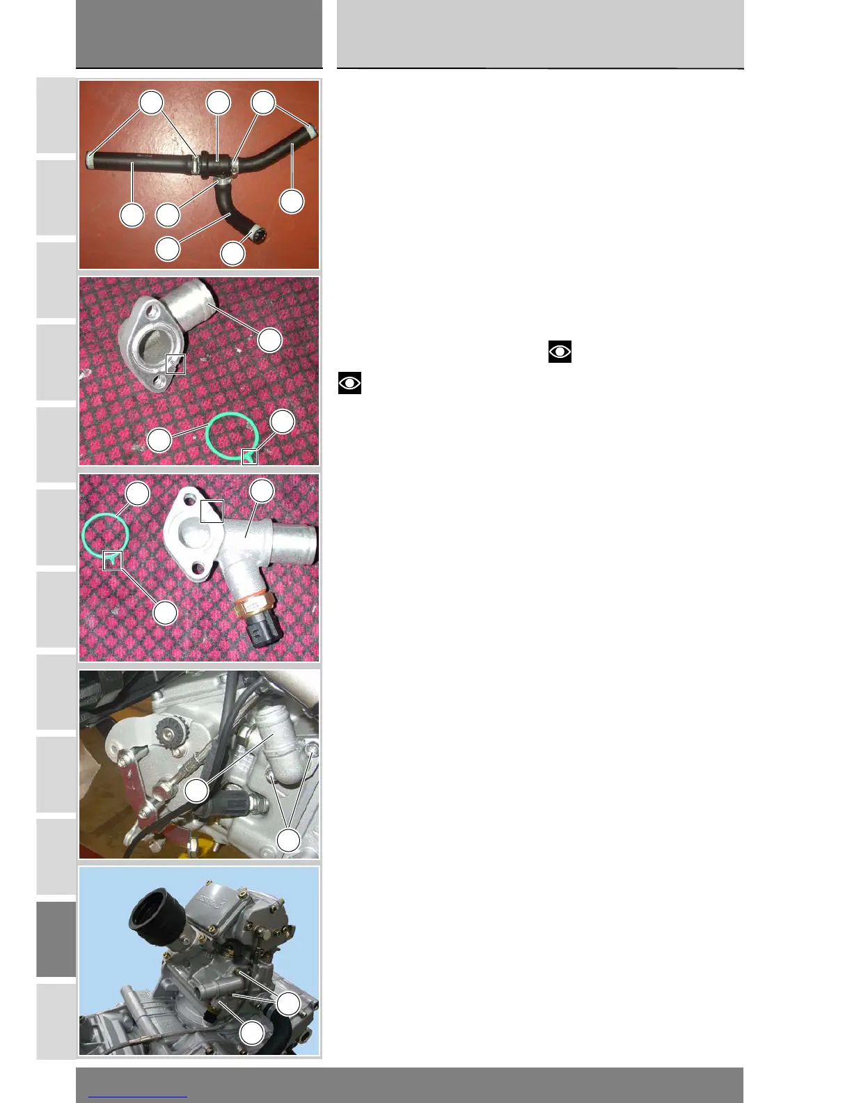
Rimontaggio tubazioni e
raccordi impianto di
raffreddamento
Ricomporre il gruppo composto da tu-
bazioni e termostato (12) manicotto
radiatore/termostato (11), manicotto
termostato/testa verticale (13), mani-
cotto termostato/testa orizzontale
(19) orientando i manicotti e le fascet-
te(10), (13) e (18) come mostrato in
figura.
Posizionare le guarnizioni OR (20) op-
portunamente lubrificate nelle sedi
dei raccordi (15) e (21).
Fare attenzione ai testimoni (G) che
siano posizionati correttamente come
mostrato in figura.
Note
Per maggiore chiarezza nelle
immagini è rappresentato un blocco
motore rimosso dal telaio, ma l'oper-
azione è comunque possibile anche
con motore montato.
Posizionare il raccordo uscita testa
verticale (15) sulla testa verticale ed
avvitare le viti di fissaggio (16).
Posizionare il raccordo uscita testa
orizzontale (21) sulla testa orizzontale
ed avvitare le viti di fissaggio (16).
Serrare le viti (16) alla coppia prescrit-
ta (Sez. C 3).
Refitting the cooling
system pipes and unions
Reassemble the hoses, thermostat
(12), radiator/thermostat hose (11),
thermostat/vertical head hose (13)
and thermostat/horizontal head hose
(19), arranging the hoses and clamps
(10), (13) and (18) as shown in the
figure.
Lubricate the O rings (20) and fit them
in their seats in the unions (15) and
(21).
Make sure that the alignment pins (G)
are correctly seated as shown in the
figure.
Note
The engine is shown removed
from the frame for purposes of clarity
alone. This operation can be
performed with the engine in place.
Fit the vertical head return union (15)
on the vertical head and screw in the
retaining screws (16).
Fit the horizontal head return union
(21) on the horizontal head and screw
in the retaining screws (16).
Tighten the retaining screws (16) to
the specified torque (Section C 3).
13 1012
14 18
11
19
18
G
20
21
15
G
20
21
16
16
15