A
B
C
D
E
F
G
H
L
M
N
P
Motore
Engine
sezione / section
N 3.2
43ST3 - M.Y. 2004 - edizione/edition 00
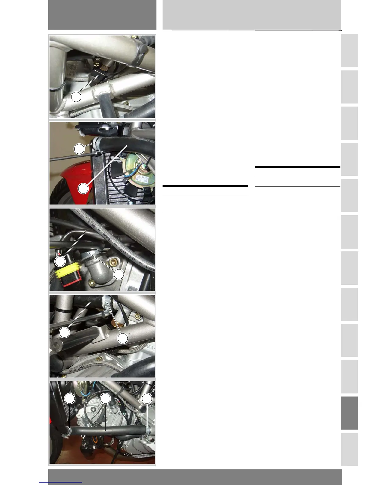
Collegare il connettore (H) del cablag-
gio principale al sensore sul raccordo
della testa verticale.
Inserire i manicotti (14), (11) e (19) ris-
pettivamente sul raccordo uscita ac-
qua testa verticale (15), sul radiatore
(4) e sul raccordo uscita acqua testa
orizzontale (21).
Serrare le fascette (10), (13) e (18) alla
coppia di serraggio prescritta (Sez. C
3).
Inserire il manicotto pompa/radiatore
(22) sul radiatore (4) e sul bocchet-
tone di uscita acqua della pompa.
Serrare le fascette (10) alla coppia
prescritta (Sez. C 3).
Per un posizionamento corretto dei
manicotti fare riferimento alle tavole
di seguito riportate.
Procedere al rimontaggio delle strut-
ture rimosse per le operazioni de-
scritte.
Operazioni Rif. Sez.
Riempire l'impianto di
raffreddamento
D 4
Rimontare le carene
laterali
E 2
Connect the connector (H) of the
main wiring harness to the
temperature sensor on the union on
the vertical head.
Fit the hoses (14), (11) and (19) to the
vertical head coolant return union
(15), radiator (4) and horizontal head
coolant return union (21) respectively.
Tighten the hose clamps (10), (13)
and (18) to the specified torque
(Section C 3).
Fit the pump/radiator hose (22) to the
radiator (4) and coolant delivery union
on the pump.
Tighten the hose clamps (10) to the
specified torque (Section C 3).
For unions correct routing, refer to
the following diagrams.
Refit all the parts previously removed.
Operations See Sect.
Fill the cooling circuit D 4
Refit the side fairings E 2
H
10
11
19
18
14
13
10 22 10