Ruote - Sospensioni - Freni
Wheels - Suspensions - Brakes
sezione / section
G 2
8
A
A
B
C
D
E
F
G
H
L
M
N
P
ST3 - M.Y. 2004 - edizione/edition 00
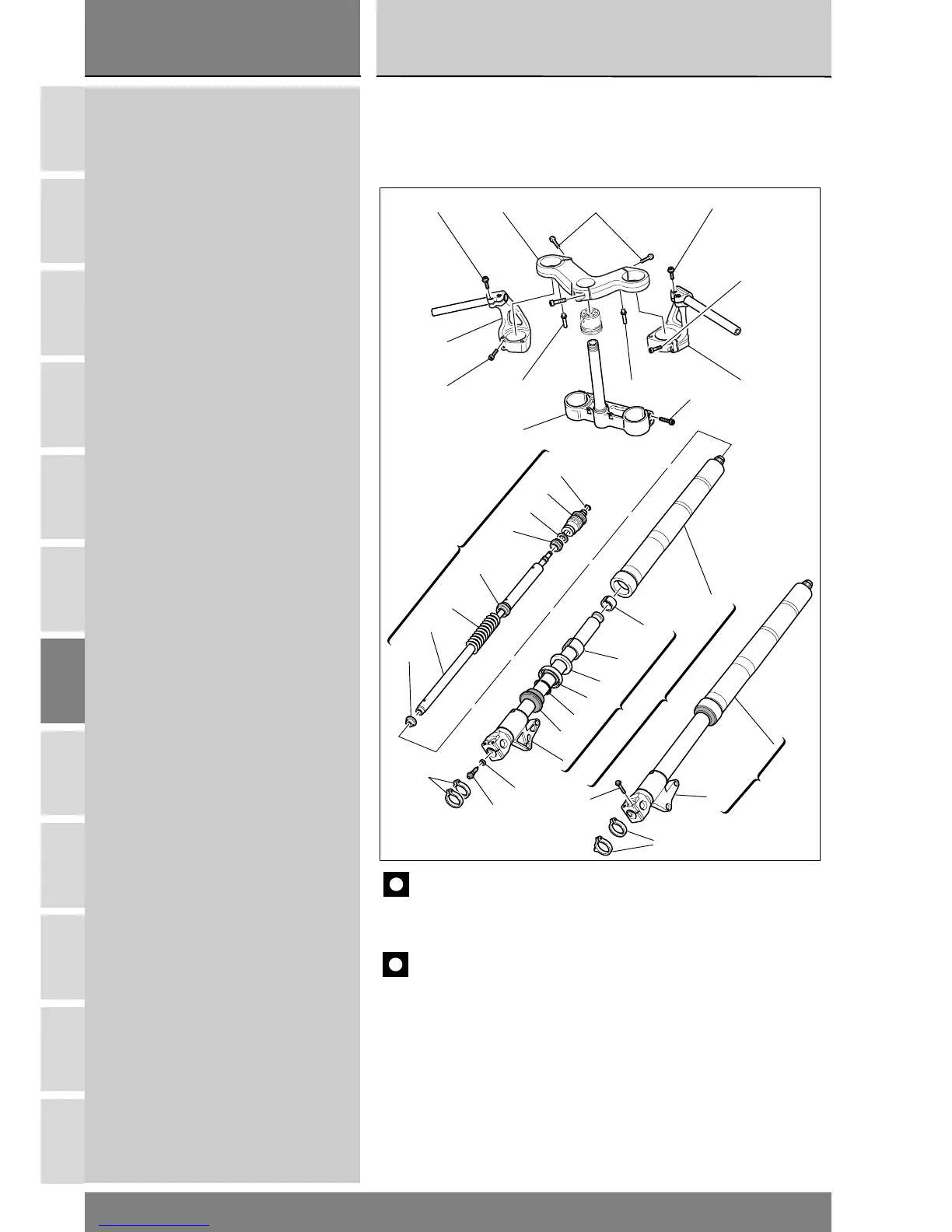
2 - FORCELLA ANTERIORE
1Vite
2Vite
3 Testa di sterzo
4 Supporto semimanubrio sinistro
5 Supporto semimanubrio destro
6 Piolo
7Vite
8 Base di sterzo
9Vite
10 Anello elastico di arresto
11 Tappo completo
12 Rosetta
13 Scorrevole
14 Vite di regolazione
15 Giunto molla
16 Molla
17 Tubo ammortizzatore
18 Anello di centraggio
19 Assieme gamba destra
20 Fodero esterno
21 Boccola
22 Boccola
23 Scodellino
24 Anello di tenuta
25 Anello
26 Parapolvere
27 Scorrevole destro completo
28 Scorrevole sinistro completo
29 Assieme gamba sinistra
30 Vite
31 Fascetta
32 Rondella speciale
2
4
7 6
8
6 5
7
9
21
10
11
12
13
3
20
21
19
27
29
28
22
23
24
25
26
15
16
17
19
18
30
32
14
31
31
2 - FRONT FORK
1 Pinch bolt
2 Pinch bolt
3 Top yoke
4 LH handlebar mounting
5 RH handlebar mounting
6Pin
7 Pinch bolt
8 Bottom yoke
9 Pinch bolt
10 Snap ring
11 Complete plug
12 Seal
13 Bush
14 Adjuster screw
15 Damper cap
16 Spring
17 Damper tube
18 Centering ring
19 Right leg assembly
20 Outer sleeve
21 Guide bush
22 Stanchion tube bush
23 Dish ring
24 Oil seal
25 Retaining ring
26 Dust seal
27 Complete right slider
28 Complete left slider
29 Left leg assembly
30 Pinch bolt
31 Clamp
32 Special washer
Caution
Bold reference numbers in this section identify parts not shown in the
figures next to the text. Look up the exploded view diagram.
Importante
I riferimenti in grassetto all’interno di questo capitolo indicano che i
particolari richiamati non sono presenti nelle immagini a fianco del testo, ma
devono essere ricercati nella presente tavola esplosa.
G