The position of image B and C in relationship to the reference image A is determined through
the Y-axis (= intersection line for image B) and through the X-axis (= intersection line for
image C). By positioning these two axes within the reference image the corresponding
parallel planes of B- and C-images are displayed automatically.
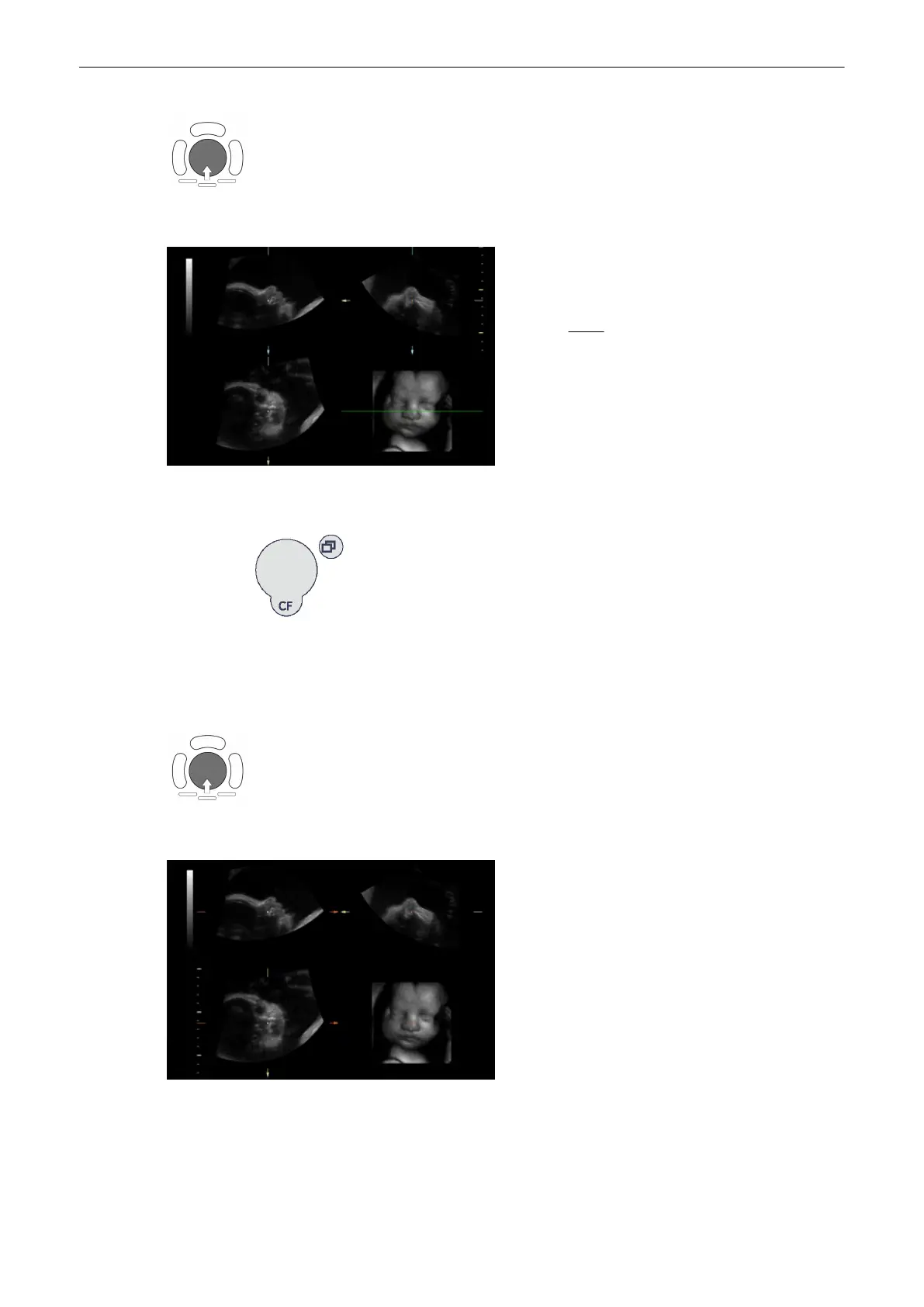
The selected reference image is sectional plane B
The spatial position of plane B in relationship to the
displayed 3D image is always horizontal and also
perpendicular to the 3D image display. Therefore the
position of image B is indicated by means of a
horizontal green line within the 3D image.
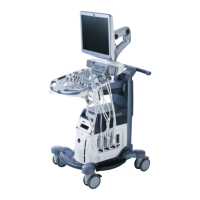
Adjust the position of the green line within the 3D image
Parallel shift control [Parallel shift] enables a parallel shifting (up/down) of the green line and
the corresponding parallel planes of image B will be displayed automatically.
Adjust the position of image A and C with trackball
The position of image A and C in relationship to the reference image B is determined through
the Y-axis (= intersection line for image A) and through the X-axis (= intersection line for
image C). By positioning these two axes within the reference image B the corresponding
parallel planes of A- and C-images are displayed automatically.
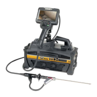
Selected reference image is sectional plane C:
The spatial position of plane C in relationship to the
displayed 3D image is always a parallel plane with a
rotation of 90˚. Therefore it is not possible to indicate
the trace of image C by means of an intersectional
line within the 3D image.
Adjust the depth-position of plane C
Volume Mode
9-56
Voluson® S6/S8 Basic User Manual
5433669-100 Revision 4