214603 183 Revision A
Figure 4.38: Lift Arms
3. Retrieve temporary lift pin from storage location on
weight box and install into rear hole (A) at the top of the
lift arms. This provides additional lift height for transport
wheel deployment.
CAUTION
Check to be sure all bystanders have cleared the area.
4. Start the engine and raise the header to full height.
5. Stop the engine and engage safety props on the lift
cylinders.
Figure 4.39: Header in Transport Mode
6. Deploy header slow speed transport system. Refer to
header operator’s manual.
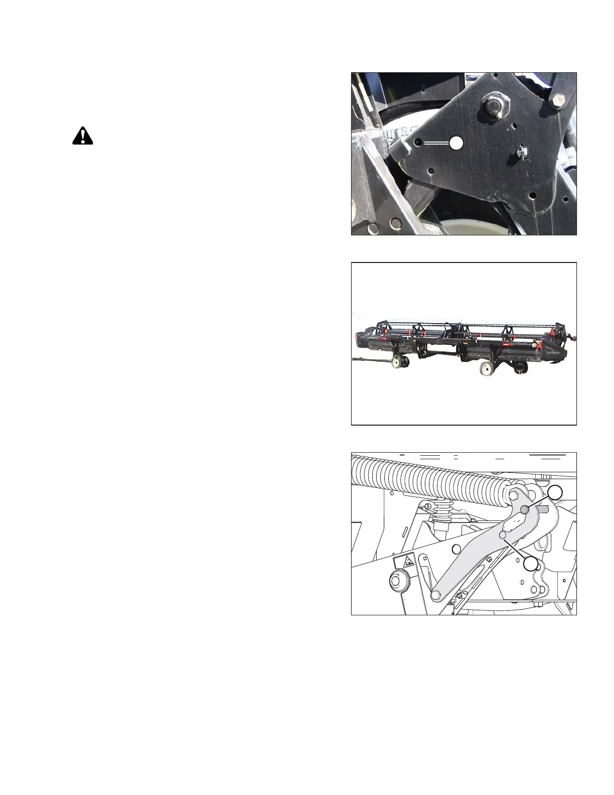
Figure 4.40: Lift Arms
7. Remove float pin from engaged position (A) and insert
in storage location (B). Secure with lynch pin.
OPERATION