214603 191 Revision A
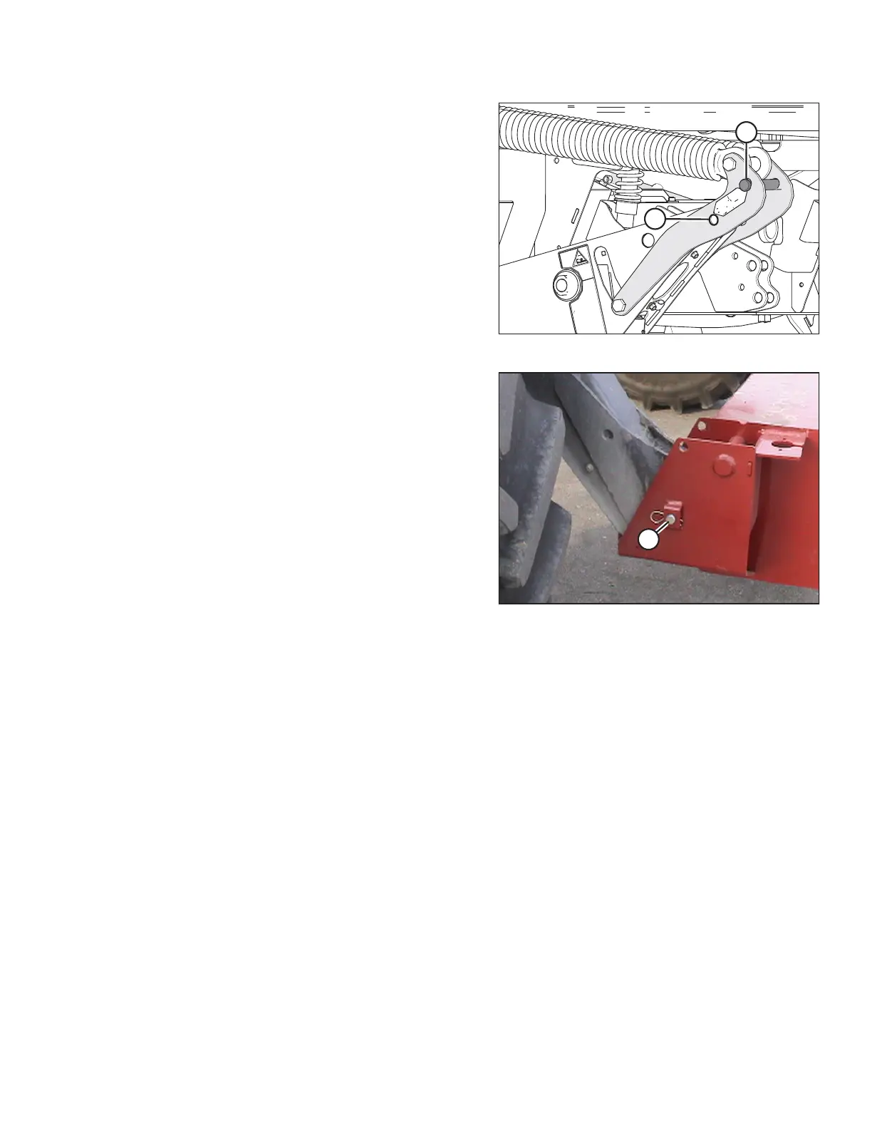
Figure 4.60: Float Pins
12. Move float pins from working hole location (A) to
disengage the float and store pins at storage hole
location (B).
IMPORTANT:
To prevent damage to the lift system when lowering
header lift linkages without a header or weight box
attached to windrower, ensure that float engagement
pin is installed in storage hole location and NOT
installed in working hole location.
Figure 4.61: Weight Box
13. Remove pins (A) securing lift linkages to weight box,
and retain pins for attaching header to windrower.
Disengage lift cylinder safety props. Refer to 4.4.1
Engaging and Disengaging Header Safety Props: M
Series Self-Propelled Windrower, page 194.
14. Start the engine, lower weight box onto blocks, and back away.
15. Attach the header to the windrower. Refer to 4.5 Attaching and Detaching Headers, page 217.
16. Convert header into field position. Refer to header operator’s manual for procedure.
17. Before operating the machine, double-check that all pins are secure and that all safety equipment is installed
and fully functional.
18. Proceed with operation of the header.
OPERATION