USB on-the-go full-speed (OTG_FS) RM0008
836/1096 Doc ID 13902 Rev 12
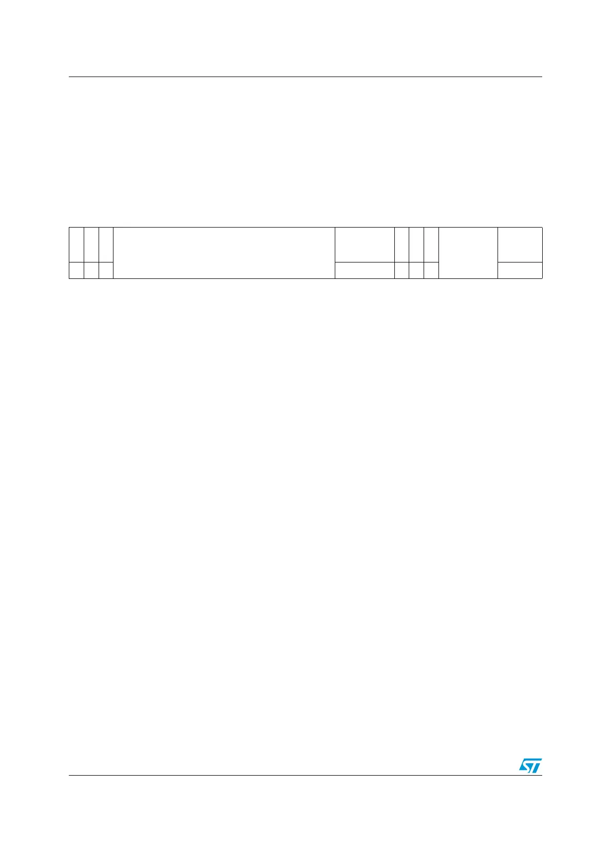
OTG_FS USB configuration register (OTG_FS_GUSBCFG)
Address offset: 0x00C
Reset value: 0x0000 0A00
This register can be used to configure the core after power-on or a changing to host mode or
device mode. It contains USB and USB-PHY related configuration parameters. The
application must program this register before starting any transactions on either the AHB or
the USB. Do not make changes to this register after the initial programming.
313029282726252423222120191817161514131211109876543210
CTXPKT
FDMOD
FHMOD
Reserved
TRDT
HNPCAP
SRPCAP
PHYSEL
Reserved
TOCAL
rw rw rw rw
r/rw
r/rw
wo rw
Bits 31:20 Reserved.
Bit 31 CTXPKT: Corrupt Tx packet
This bit is for debug purposes only. Never set this bit to 1.
Note: Accessible in both device and host modes.
Bit 30 FDMOD: Force device mode
Writing a 1 to this bit forces the core to device mode irrespective of the OTG_FS_ID input pin.
0: Normal mode
1: Force device mode
After setting the force bit, the application must wait at least 25 ms before the change takes
effect.
Note: Accessible in both device and host modes.
Bit 29 FHMOD: Force host mode
Writing a 1 to this bit forces the core to host mode irrespective of the OTG_FS_ID input pin.
0: Normal mode
1: Force host mode
After setting the force bit, the application must wait at least 25 ms before the change takes
effect.
Note: Accessible in both device and host modes.
Bits 28:14 Reserved
Bits 13:10 TRDT: USB turnaround time
Sets the turnaround time in PHY clocks.
To calculate the value of TRDT, use the following formula:
TRDT = 4 × AHB clock + 1 PHY clock
Examples:
1. if AHB clock = 72 MHz (PHY Clock is 48), the TRDT is set to 9.
2. if AHB clock = 48 MHz (PHY Clock is 48), the TRDT is set to 5.
Note: Only accessible in device mode.
Bit 9 HNPCAP: HNP-capable
The application uses this bit to control the OTG_FS controller’s HNP capabilities.
0: HNP capability is not enabled.
1: HNP capability is enabled.
Note: Accessible in both device and host modes.

 Loading...


