RM0090 Rev 18 1085/1749
RM0090 Controller area network (bxCAN)
1121
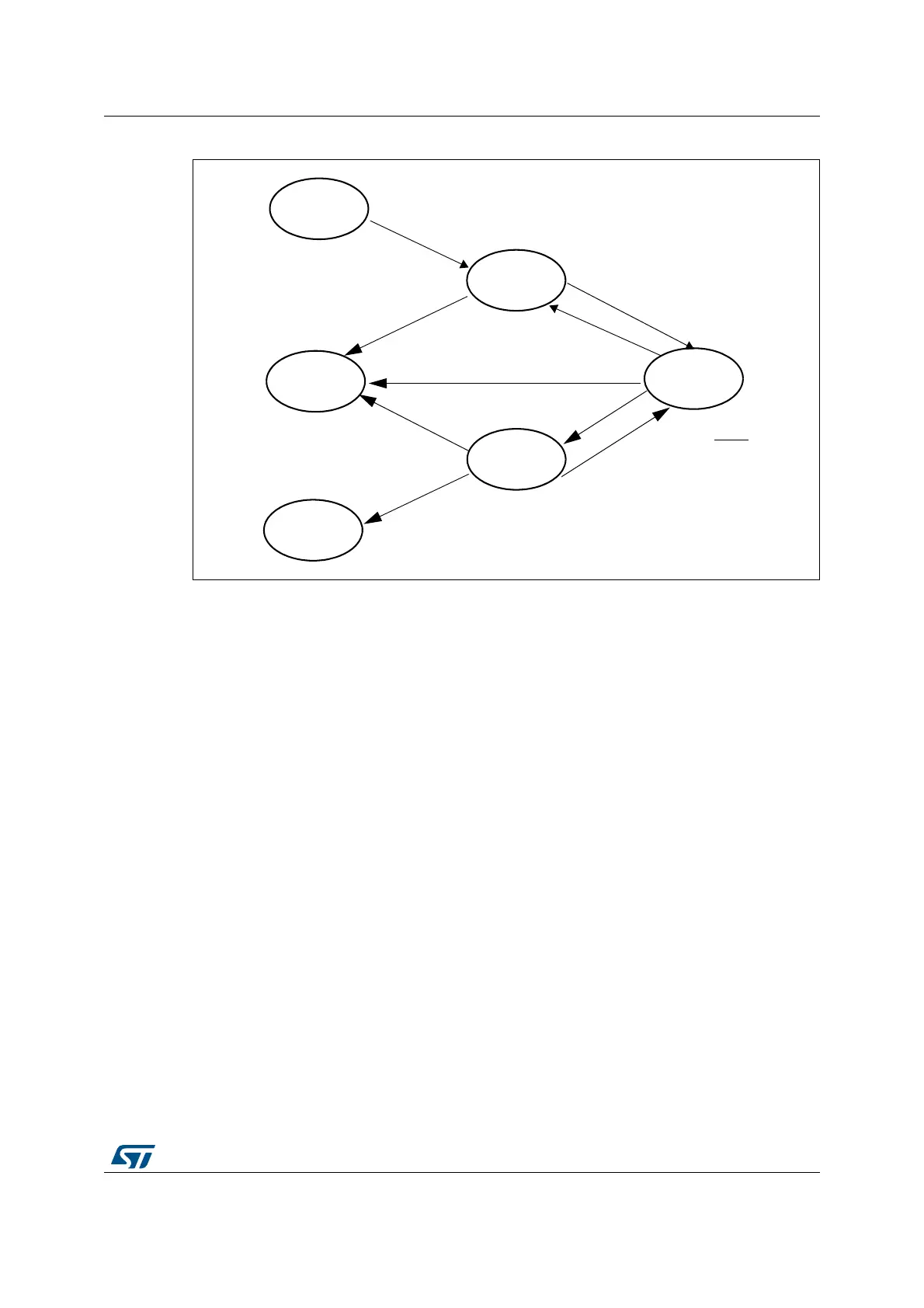
Figure 340. Transmit mailbox states
32.7.2 Time triggered communication mode
In this mode, the internal counter of the CAN hardware is activated and used to generate the
Time Stamp value stored in the CAN_RDTxR/CAN_TDTxR registers, respectively (for Rx
and Tx mailboxes). The internal counter is incremented each CAN bit time (refer to
Section 32.7.7). The internal counter is captured on the sample point of the Start Of Frame
bit in both reception and transmission.
32.7.3 Reception handling
For the reception of CAN messages, three mailboxes organized as a FIFO are provided. In
order to save CPU load, simplify the software and guarantee data consistency, the FIFO is
managed completely by hardware. The application accesses the messages stored in the
FIFO through the FIFO output mailbox.
Valid message
A received message is considered as valid when it has been received correctly according to
the CAN protocol (no error until the last but one bit of the EOF field) and It passed through
the identifier filtering successfully, see Section 32.7.4.
EMPTY
TXRQ=1
RQCP=X
TXOK=X
PENDING
RQCP=0
TXOK=0
SCHEDULED
RQCP=0
TXOK=0
Mailbox has
TRANSMIT
RQCP=0
TXOK=0
CAN Bus = IDLE
Transmit failed * NART
Transmit succeeded
Mailbox does not
EMPTY
RQCP=1
TXOK=0
highest priority
have highest priority
EMPTY
RQCP=1
TXOK=1
ABRQ=1
ABRQ=1
Transmit failed * NART
TME = 1
TME = 0
TME = 0
TME = 0
TME = 1
TME = 1