Advanced-control timers (TIM1 and TIM8) RM0090
536/1749 RM0090 Rev 18
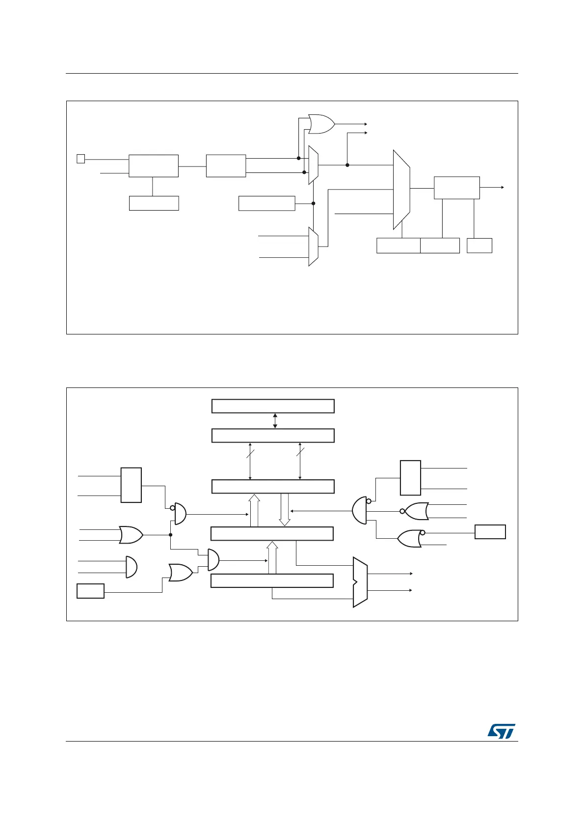
Figure 112. Capture/compare channel (example: channel 1 input stage)
The output stage generates an intermediate waveform that is then used for reference:
OCxRef (active high). The polarity acts at the end of the chain.
Figure 113. Capture/compare channel 1 main circuit
0
1
Divider
/1, /2, /4, /8
ICPS[1:0]
TI1F_ED
To the slave mode controller
TI1FP1
11
01
CC1S[1:0]
IC1
TI2FP1
TRC
(from slave mode
controller)
10
IC1PS
0
1
MS33115V1
TI1
TIMx_CCER
CC1P/CC1NP
Filter
downcounter
ICF[3:0]
TIMx_CCMR1
Edge
detector
TI1F_Rising
TI1F_Falling
TIMx_CCMR1
TIMx_CCER
TI2F_Rising
(from channel 2)
TI2F_Falling
(from channel 2)
TI1F
f
CC1E
DTS
MS31089V3
CC1E
Capture/compare shadow register
Comparator
Capture/compare preload register
Counter
IC1PS
CC1S[0]
CC1S[1]
Capture
Input
mode
S
R
Read CCR1H
Read CCR1L
read_in_progress
capture_transfer
CC1S[0]
CC1S[1]
S
R
write CCR1H
write CCR1L
write_in_progress
Output
mode
UEV
OC1PE
(from time
base unit)
compare_transfer
APB Bus
8
8
high
low
(if 16-bit)
MCU-peripheral interface
TIMx_CCMR1
OC1PE
CNT>CCR1
CNT=CCR1
TIMx_EGR
CC1G