Serial peripheral interface (SPI) RM0090
908/1749 RM0090 Rev 18
Figure 281. Audio sampling frequency definition
When the master mode is configured, a specific action needs to be taken to properly
program the linear divider in order to communicate with the desired audio frequency.
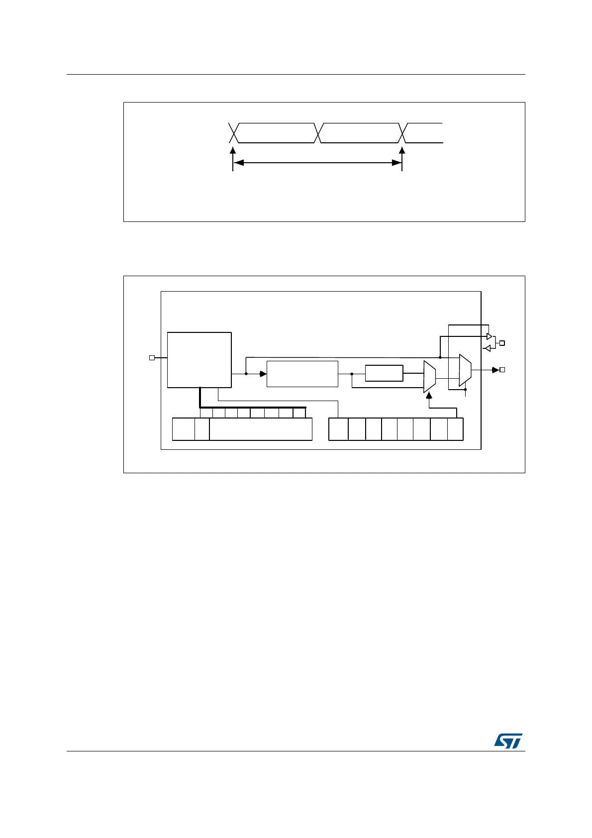
Figure 282. I
2
S clock generator architecture
1. Where x could be 2 or 3.
Figure 281 presents the communication clock architecture. To achieve high-quality audio
performance, the I2SxCLK clock source can be either the PLLI2S output (through R division
factor) or an external clock (mapped to I2S_CKIN pin).
The audio sampling frequency can be 192 kHz, 96 kHz, or 48 kHz. In order to reach the
desired frequency, the linear divider needs to be programmed according to the formulas
below:
When the master clock is generated (MCKOE in the SPI_I2SPR register is set):
F
S
= I2SxCLK / [(16*2)*((2*I2SDIV)+ODD)*8)] when the channel frame is 16-bit wide
F
S
= I2SxCLK / [(32*2)*((2*I2SDIV)+ODD)*4)] when the channel frame is 32-bit wide
When the master clock is disabled (MCKOE bit cleared):
F
S
= I2SxCLK / [(16*2)*((2*I2SDIV)+ODD))] when the channel frame is 16-bit wide
F
S
= I2SxCLK / [(32*2)*((2*I2SDIV)+ODD))] when the channel frame is 32-bit wide
Table 127 provides example precision values for different clock configurations.
Note: Other configurations are possible that allow optimum clock precision.
MS30108V1
16-or 32-bit left
channel
16-or 32-bit
right channel
32- or 64-bits
sampling point
sampling point
F
S
F
S
: audio sampling frequency
MS30109V1
MCKOE
ODD
8-bit linear divider
+ reshaping stage
Divider by 4
Div2
I²SDIV[7:0]
I²SMOD
CHLEN
0
1
0
1
MCKOE
CK
MCK
I²SxCLK