Digital camera interface (DCMI) RM0090
464/1749 RM0090 Rev 18
Figure 78. Coordinates and size of the window after cropping
These registers specify the coordinates of the starting point of the capture window as a line
number (in the frame, starting from 0) and a number of pixel clocks (on the line, starting from
0), and the size of the window as a line number and a number of pixel clocks. The CAPCNT
value can only be a multiple of 4 (two least significant bits are forced to 0) to allow the
correct transfer of data through the DMA.
If the VSYNC signal goes active before the number of lines is specified in the
DCMI_CWSIZE register, then the capture stops and an IT_FRAME interrupt is generated
when enabled.
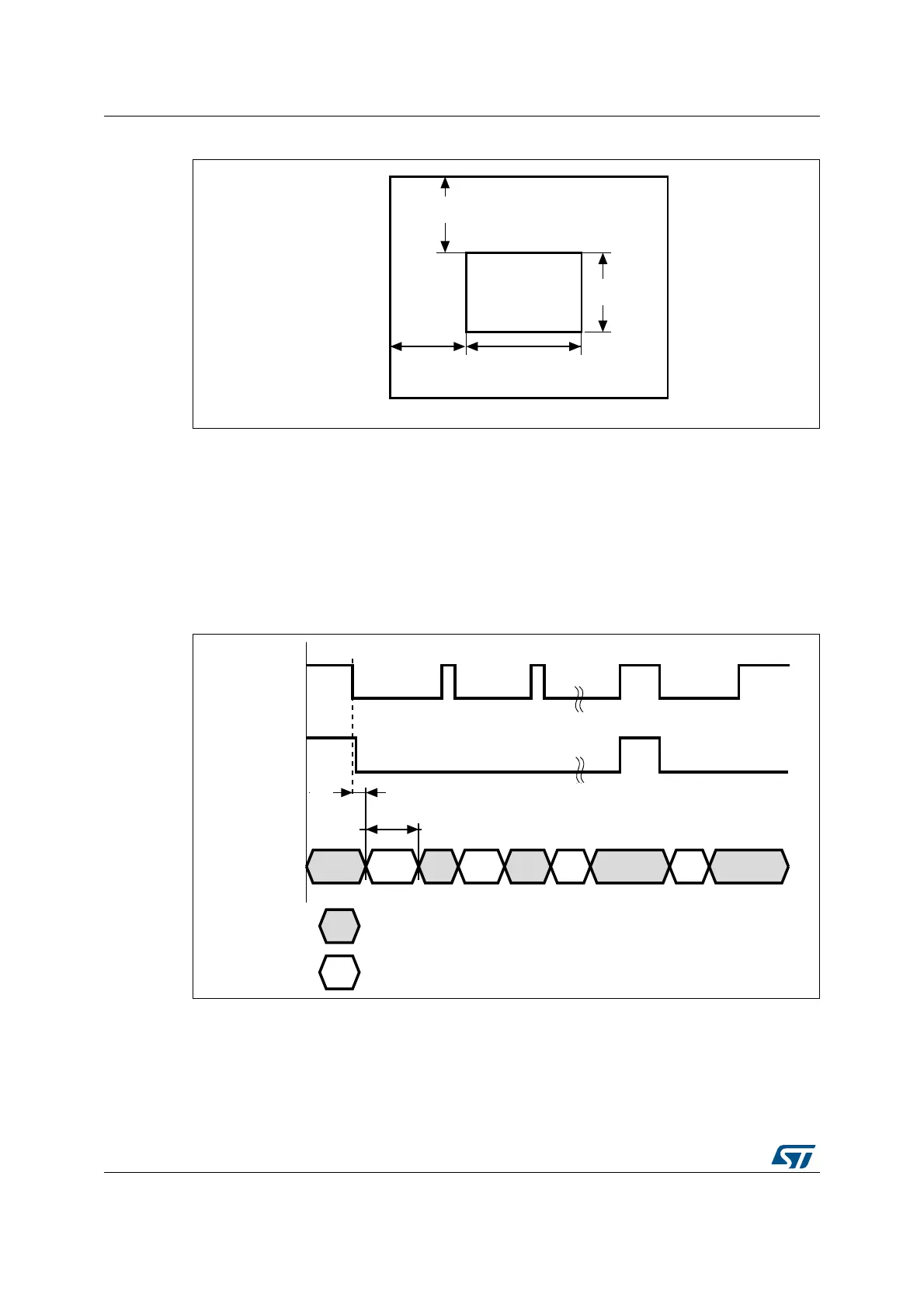
Figure 79. Data capture waveforms
1. Here, the active state of DCMI_HSYNC and DCMI_VSYNC is 1.
2. DCMI_HSYNC and DCMI_VSYNC can change states at the same time.
CAPCNT bit in DCMI_CSIZE
HOFFCNT bit in DCMI_CSTRT
ai15834
VST bit in DCMI_CSTRT
VLINE bit in DCMI_CSIZE
DCMI_HSYNC
DCMI_VSYNC
ai15835
CAPCNT
HOFFCNT
Data not captured in this phase
Data captured in this phase