General-purpose timers (TIM9 to TIM14) RM0090
660/1749 RM0090 Rev 18
19.3.4 Capture/compare channels
Each Capture/Compare channel is built around a capture/compare register (including a
shadow register), a input stage for capture (with digital filter, multiplexing and prescaler) and
an output stage (with comparator and output control).
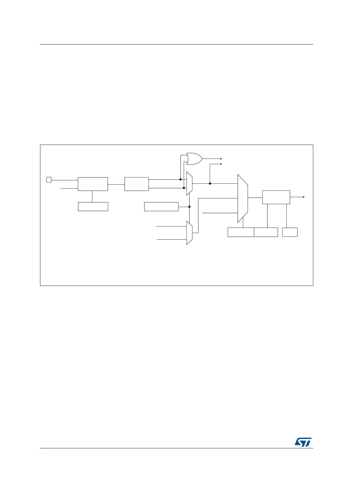
Figure 193 to Figure 195 give an overview of a capture/compare channel.
The input stage samples the corresponding TIx input to generate a filtered signal TIxF.
Then, an edge detector with polarity selection generates a signal (TIxFPx) which can be
used as trigger input by the slave mode controller or as the capture command. It is
prescaled before the capture register (ICxPS).
Figure 193. Capture/compare channel (example: channel 1 input stage)
The output stage generates an intermediate waveform which is then used for reference:
OCxRef (active high). The polarity acts at the end of the chain.
0
1
Divider
/1, /2, /4, /8
ICPS[1:0]
TI1F_ED
To the slave mode controller
TI1FP1
11
01
CC1S[1:0]
IC1
TI2FP1
TRC
(from slave mode
controller)
10
IC1PS
0
1
MS33115V1
TI1
TIMx_CCER
CC1P/CC1NP
Filter
downcounter
ICF[3:0]
TIMx_CCMR1
Edge
detector
TI1F_Rising
TI1F_Falling
TIMx_CCMR1
TIMx_CCER
TI2F_Rising
(from channel 2)
TI2F_Falling
(from channel 2)
TI1F
f
CC1E
DTS