RM0090 Rev 18 529/1749
RM0090 Advanced-control timers (TIM1 and TIM8)
588
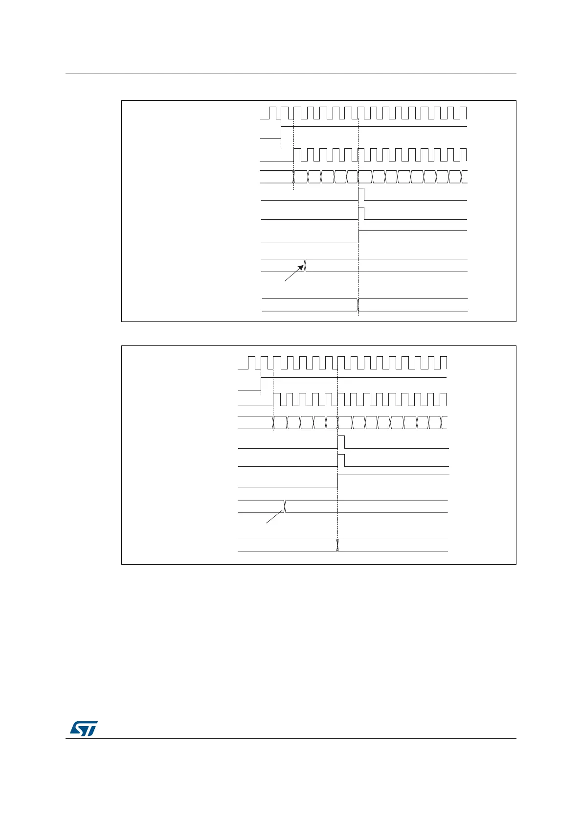
Figure 104. Counter timing diagram, update event with ARPE=1 (counter underflow)
Figure 105. Counter timing diagram, Update event with ARPE=1 (counter overflow)
17.3.3 Repetition counter
Section 17.3.1: Time-base unit describes how the update event (UEV) is generated with
respect to the counter overflows/underflows. It is actually generated only when the repetition
counter has reached zero. This can be useful when generating PWM signals.
This means that data are transferred from the preload registers to the shadow registers
(TIMx_ARR auto-reload register, TIMx_PSC prescaler register, but also TIMx_CCRx
capture/compare registers in compare mode) every N+1 counter overflows or underflows,
where N is the value in the TIMx_RCR repetition counter register.
MS31193V3
CK_PSC
Timer clock = CK_CNT
Counter register
Update event (UEV)
Counter overflow
Update interrupt flag (UIF)
CEN
Auto-reload preload register
Write a new value in TIMx_ARR
Auto-reload active register
FD 36
00 02 03 04 05 06 070106 05 04 03 02 01
FD 36
MS31194V2
FD 36
CK_PSC
Timer clock = CK_CNT
Counter register
Update event (UEV)
Counter overflow
Update interrupt flag (UIF)
36 34 33 32 31 30 2FF8 F9 FA FB FCF7 35
CEN
Auto-reload preload register
Write a new value in TIMx_ARR
Auto-reload active register
FD 36