RM0090 Rev 18 613/1749
RM0090 General-purpose timers (TIM2 to TIM5)
649
in the TIMx_CR1 register. Moreover, the DIR and CMS bits must not be changed at the
same time by the software.
• Writing to the counter while running in center-aligned mode is not recommended as it
can lead to unexpected results. In particular:
– The direction is not updated if the user writes a value in the counter that is greater
than the auto-reload value (TIMx_CNT>TIMx_ARR). For example, if the counter
was counting up, it continues to count up.
– The direction is updated if the user writes 0 or write the TIMx_ARR value in the
counter but no Update Event UEV is generated.
• The safest way to use center-aligned mode is to generate an update by software
(setting the UG bit in the TIMx_EGR register) just before starting the counter and not to
write the counter while it is running.
18.3.10 One-pulse mode
One-pulse mode (OPM) is a particular case of the previous modes. It allows the counter to
be started in response to a stimulus and to generate a pulse with a programmable length
after a programmable delay.
Starting the counter can be controlled through the slave mode controller. Generating the
waveform can be done in output compare mode or PWM mode. Select One-pulse mode by
setting the OPM bit in the TIMx_CR1 register. This makes the counter stop automatically at
the next update event UEV.
A pulse can be correctly generated only if the compare value is different from the counter
initial value. Before starting (when the timer is waiting for the trigger), the configuration must
be:
• In upcounting: CNT<CCRx≤ARR (in particular, 0<CCRx),
• In downcounting: CNT>CCRx.
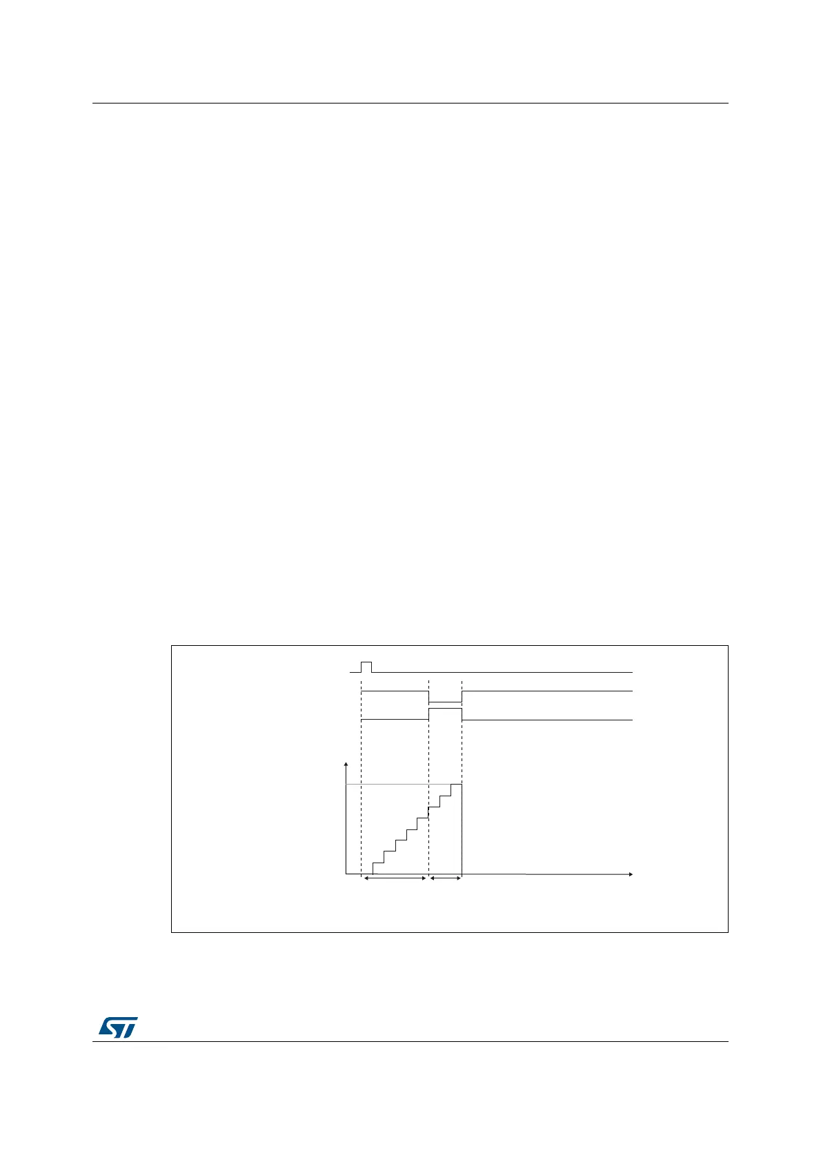
Figure 166. Example of one-pulse mode
For example the user may want to generate a positive pulse on OC1 with a length of t
PULSE
and after a delay of t
DELAY
as soon as a positive edge is detected on the TI2 input pin.
MS31099V1
TI2
OC1REF
Counter
t
0
TIM1_ARR
TIM1_CCR1
OC1
t
DELAY
t
PULSE