General-purpose timers (TIM2 to TIM5) RM0090
622/1749 RM0090 Rev 18
For example, the user can configure Timer 1 to act as a prescaler for Timer 2 (see
Figure 174). To do this:
• Configure Timer 1 in master mode so that it outputs a periodic trigger signal on each
update event UEV. If you write MMS=010 in the TIM1_CR2 register, a rising edge is
output on TRGO1 each time an update event is generated.
• To connect the TRGO1 output of Timer 1 to Timer 2, Timer 2 must be configured in
slave mode using ITR0 as internal trigger. You select this through the TS bits in the
TIM2_SMCR register (writing TS=000).
• Then you put the slave mode controller in external clock mode 1 (write SMS=111 in the
TIM2_SMCR register). This causes Timer 2 to be clocked by the rising edge of the
periodic Timer 1 trigger signal (which correspond to the timer 1 counter overflow).
• Finally both timers must be enabled by setting their respective CEN bits (TIMx_CR1
register).
Note: If OCx is selected on Timer 1 as trigger output (MMS=1xx), its rising edge is used to clock
the counter of timer 2.
Using one timer to enable another timer
In this example, we control the enable of Timer 2 with the output compare 1 of Timer 1.
Refer to Figure 174 for connections. Timer 2 counts on the divided internal clock only when
OC1REF of Timer 1 is high. Both counter clock frequencies are divided by 3 by the
prescaler compared to CK_INT (f
CK_CNT
= f
CK_INT
/3).
• Configure Timer 1 master mode to send its Output Compare 1 Reference (OC1REF)
signal as trigger output (MMS=100 in the TIM1_CR2 register).
• Configure the Timer 1 OC1REF waveform (TIM1_CCMR1 register).
• Configure Timer 2 to get the input trigger from Timer 1 (TS=000 in the TIM2_SMCR
register).
• Configure Timer 2 in gated mode (SMS=101 in TIM2_SMCR register).
• Enable Timer 2 by writing ‘1 in the CEN bit (TIM2_CR1 register).
• Start Timer 1 by writing ‘1 in the CEN bit (TIM1_CR1 register).
Note: The counter 2 clock is not synchronized with counter 1, this mode only affects the Timer 2
counter enable signal.
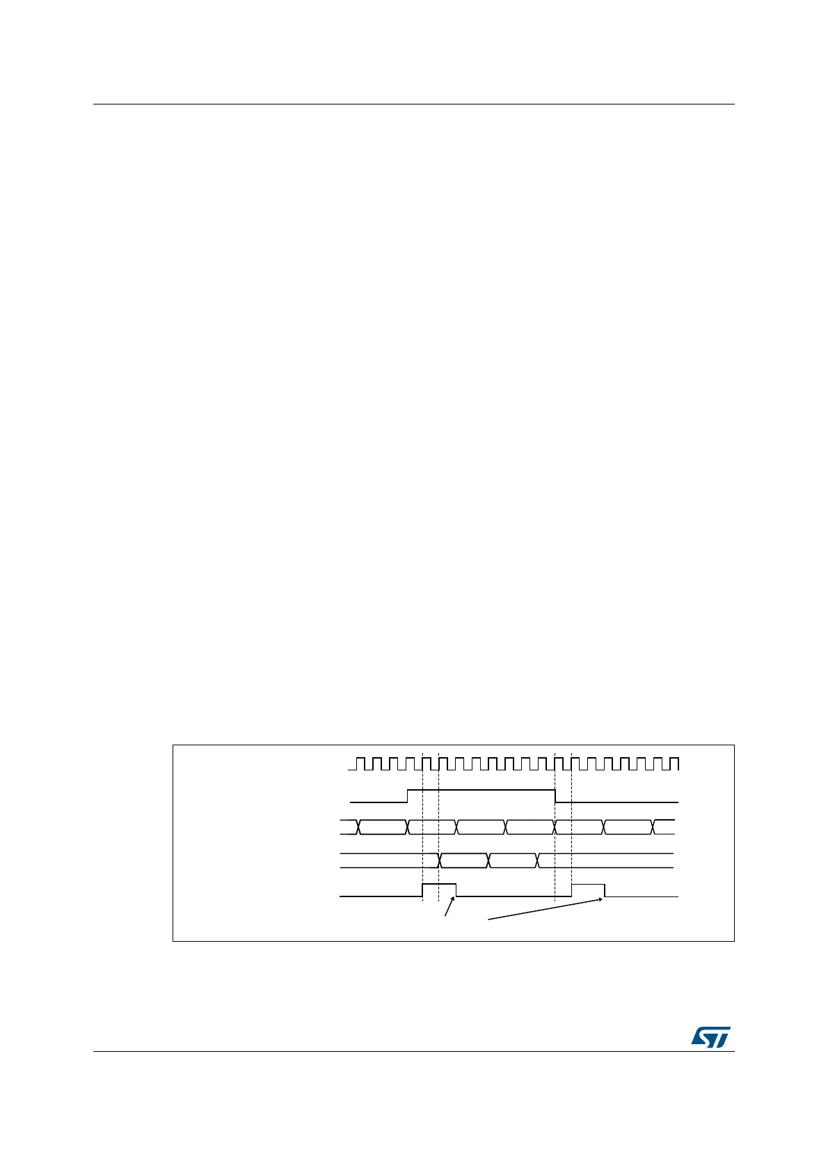
Figure 175. Gating timer 2 with OC1REF of timer 1
In the example in Figure 175, the Timer 2 counter and prescaler are not initialized before
being started. So they start counting from their current value. It is possible to start from a
given value by resetting both timers before starting Timer 1. You can then write any value
MS37388V1
CK_INT
FC FD FE FF 00 01
TIMER1-OC1REF
TIMER1-CNT
30463045 3047 3048
TIMER2-CNT
TIMER2-TIF
Write TIF = 0