RM0090 Rev 18 543/1749
RM0090 Advanced-control timers (TIM1 and TIM8)
588
TIMx_CR1 register is updated by hardware and must not be changed by software. Refer to
Center-aligned mode (up/down counting).
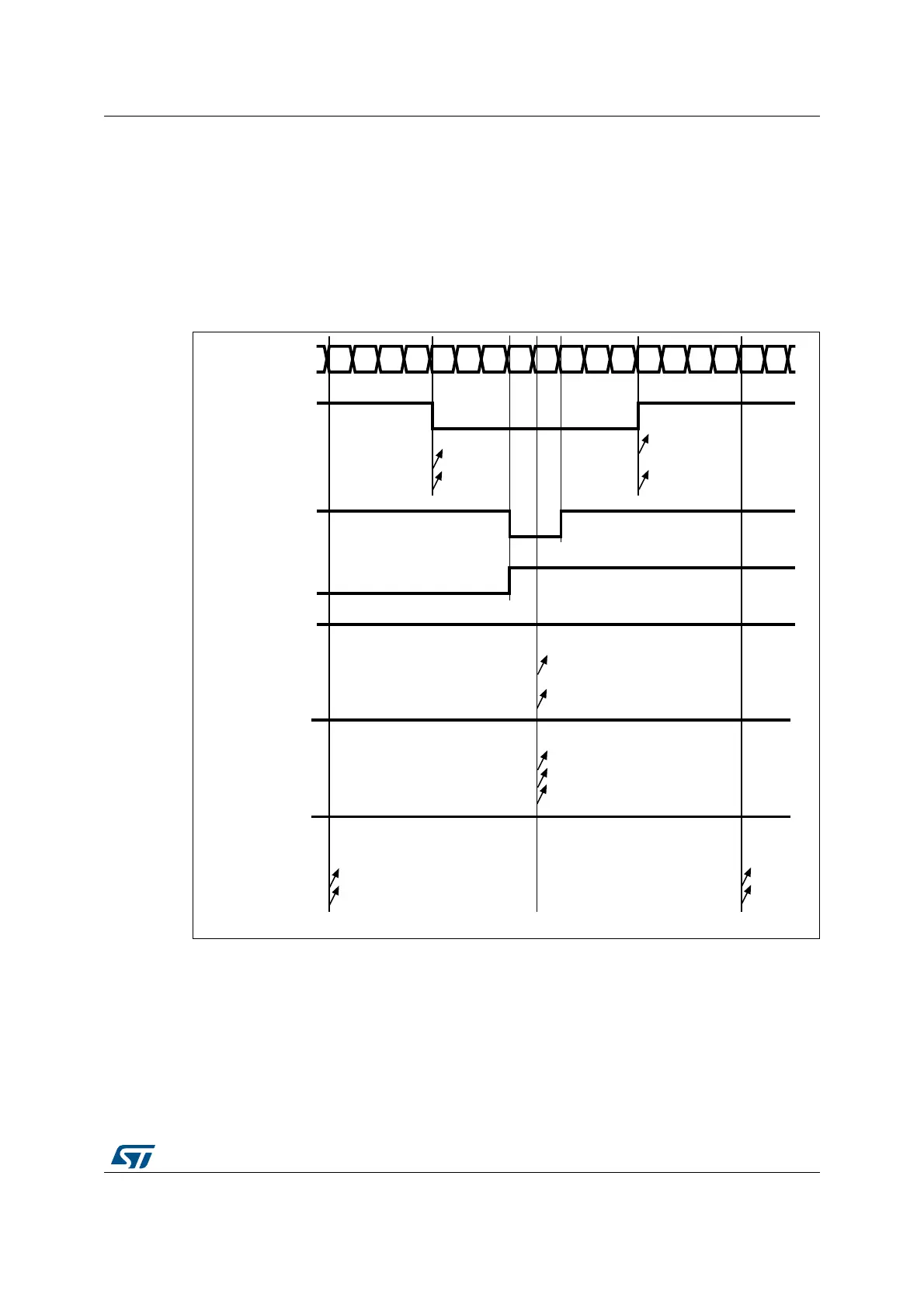
Figure 119 shows some center-aligned PWM waveforms in an example where:
• TIMx_ARR=8,
• PWM mode is the PWM mode 1,
• The flag is set when the counter counts down corresponding to the center-aligned
mode 1 selected for CMS=01 in TIMx_CR1 register.
Figure 119. Center-aligned PWM waveforms (ARR=8)
Hints on using center-aligned mode:
• When starting in center-aligned mode, the current up-down configuration is used. It
means that the counter counts up or down depending on the value written in the DIR bit
CCxIF
012345678765432101Counter register
CCRx = 4
OCxREF
CMS=01
CMS=10
CMS=11
CCxIF
CCRx = 7
OCxREF
CMS=10 or 11
CCxIF
CCRx = 8
OCxREF
CMS=01
CMS=10
CMS=11
'1'
CCxIF
CCRx > 8
OCxREF
CMS=01
CMS=10
CMS=11
'1'
CCxIF
CCRx = 0
OCxREF
CMS=01
CMS=10
CMS=11
'0'
ai14681b