RM0090 Rev 18 533/1749
RM0090 Advanced-control timers (TIM1 and TIM8)
588
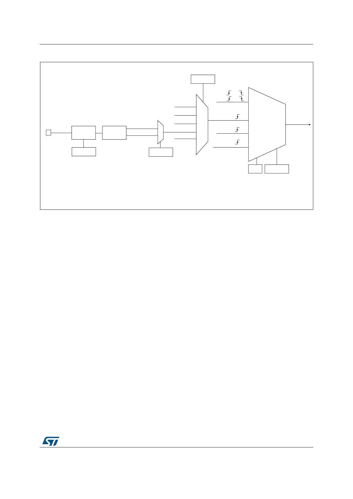
Figure 108. TI2 external clock connection example
For example, to configure the upcounter to count in response to a rising edge on the TI2
input, use the following procedure:
1. Configure channel 2 to detect rising edges on the TI2 input by writing CC2S = ‘01’ in
the TIMx_CCMR1 register.
2. Configure the input filter duration by writing the IC2F[3:0] bits in the TIMx_CCMR1
register (if no filter is needed, keep IC2F=0000).
3. Select rising edge polarity by writing CC2P=0 and CC2NP=0 in the TIMx_CCER
register.
4. Configure the timer in external clock mode 1 by writing SMS=111 in the TIMx_SMCR
register.
5. Select TI2 as the trigger input source by writing TS=110 in the TIMx_SMCR register.
6. Enable the counter by writing CEN=1 in the TIMx_CR1 register.
Note: The capture prescaler is not used for triggering, so the user does not need to configure it.
When a rising edge occurs on TI2, the counter counts once and the TIF flag is set.
The delay between the rising edge on TI2 and the actual clock of the counter is due to the
resynchronization circuit on TI2 input.
External clock
mode 1
Internal clock
mode
TRGI
CK_INT
CK_PSC
TIMx_SMCR
SMS[2:0]
ITRx
TI1_ED
TI1FP1
TI2FP2
TIMx_SMCR
TS[2:0]
TI2
0
1
TIMx_CCER
CC2P
Filter
ICF[3:0]
TIMx_CCMR1
Edge
detector
TI2F_Rising
TI2F_Falling
110
0xx
100
101
MS31196V1
(internal clock)
TI1F or
TI2F or
or
Encoder
mode
ETRF
111
External clock
mode 2
ETRF
ECE