Serial peripheral interface (SPI) RM0090
900/1749 RM0090 Rev 18
The I
2
S shares three common pins with the SPI:
• SD: Serial Data (mapped on the MOSI pin) to transmit or receive the two time-
multiplexed data channels (in half-duplex mode only).
• WS: Word Select (mapped on the NSS pin) is the data control signal output in master
mode and input in slave mode.
• CK: Serial Clock (mapped on the SCK pin) is the serial clock output in master mode
and serial clock input in slave mode.
• I2S2ext_SD and I2S3ext_SD: additional pins (mapped on the MISO pin) to control the
I
2
S full duplex mode.
An additional pin could be used when a master clock output is needed for some external
audio devices:
• MCK: Master Clock (mapped separately) is used, when the I
2
S is configured in master
mode (and when the MCKOE bit in the SPI_I2SPR register is set), to output this
additional clock generated at a preconfigured frequency rate equal to 256 × F
S
, where
F
S
is the audio sampling frequency.
The I
2
S uses its own clock generator to produce the communication clock when it is set in
master mode. This clock generator is also the source of the master clock output. Two
additional registers are available in I
2
S mode. One is linked to the clock generator
configuration SPI_I2SPR and the other one is a generic I
2
S configuration register
SPI_I2SCFGR (audio standard, slave/master mode, data format, packet frame, clock
polarity, etc.).
The SPI_CR1 register and all CRC registers are not used in the I
2
S mode. Likewise, the
SSOE bit in the SPI_CR2 register and the MODF and CRCERR bits in the SPI_SR are not
used.
The I
2
S uses the same SPI register for data transfer (SPI_DR) in 16-bit wide mode.
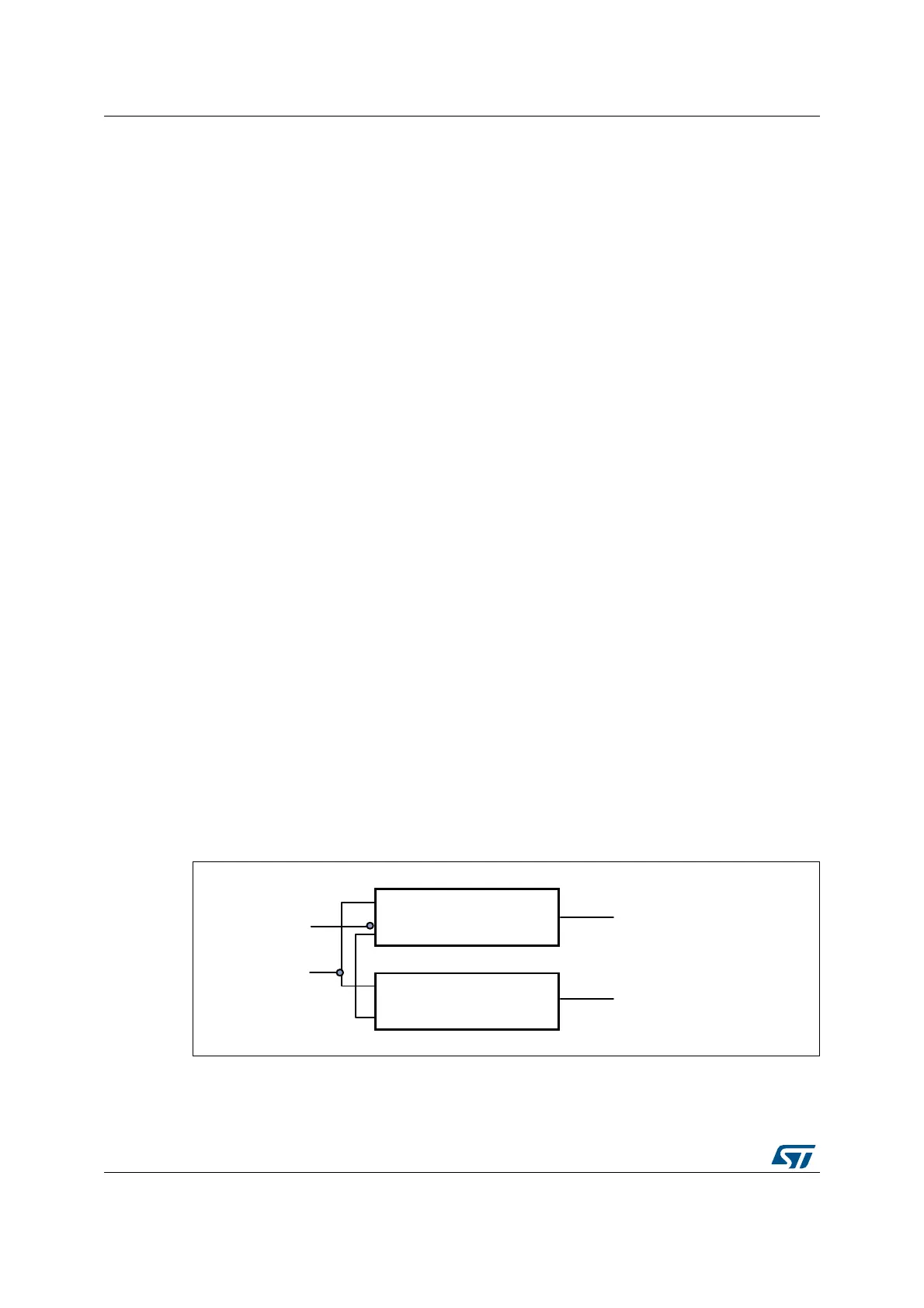
28.4.2 I2S full duplex
To support I2S full duplex mode, two extra I
2
S instances called extended I2Ss (I2S2_ext,
I2S3_ext) are available in addition to I2S2 and I2S3 (see Figure 263). The first I2S full-
duplex interface is consequently based on I2S2 and I2S2_ext, and the second one on I2S3
and I2S3_ext.
Note: I2S2_ext an I2S3_ext are used only in full-duplex mode.
Figure 263. I2S full duplex block diagram
1. Where x can be 2 or 3.
MS19910V1
SPI/I2Sx
I2Sx_ext
SPIx_MOSI/I2Sx_SD(in/out)
I2S_ WS
I2Sx_SCK
I2Sx_extSD(in/out)