General-purpose timers (TIM9 to TIM14) RM0090
658/1749 RM0090 Rev 18
19.3.3 Clock selection
The counter clock can be provided by the following clock sources:
• Internal clock (CK_INT)
• External clock mode1 (for TIM9 and TIM12): external input pin (TIx)
• Internal trigger inputs (ITRx) (for TIM9 and TIM12): connecting the trigger output from
another timer. Refer to Using one timer as prescaler for another timer for more details.
Internal clock source (CK_INT)
The internal clock source is the default clock source for TIM10/TIM11 and TIM13/TIM14.
For TIM9 and TIM12, the internal clock source is selected when the slave mode controller is
disabled (SMS=’000’). The CEN bit in the TIMx_CR1 register and the UG bit in the
TIMx_EGR register are then used as control bits and can be changed only by software
(except for UG which remains cleared). As soon as the CEN bit is programmed to 1, the
prescaler is clocked by the internal clock CK_INT.
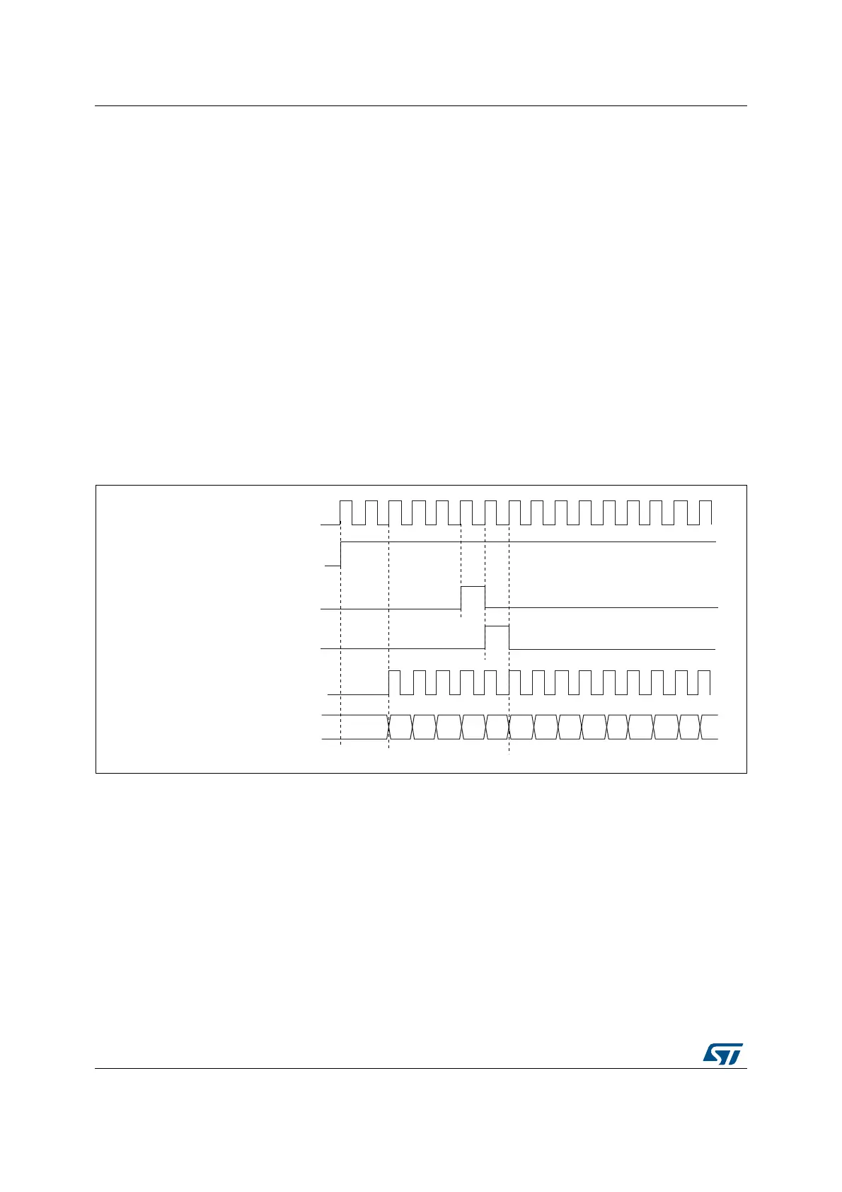
Figure 190 shows the behavior of the control circuit and of the upcounter in normal mode,
without prescaler.
Figure 190. Control circuit in normal mode, internal clock divided by 1
External clock source mode 1(TIM9 and TIM12)
This mode is selected when SMS=’111’ in the TIMx_SMCR register.
The counter can count
at each rising or falling edge on a selected input.
Internal clock
Counter clock = CK_CNT = CK_PSC
Counter register
CEN=CNT_EN
UG
CNT_INIT
MS31085V2
00 02
03
04 05
06 0732
33
34 35 36
31
01