Serial peripheral interface (SPI) RM0090
902/1749 RM0090 Rev 18
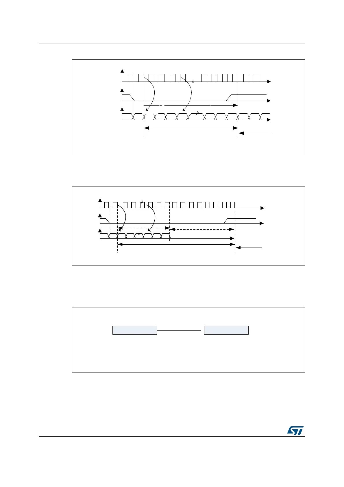
Figure 264. I
2
S Philips protocol waveforms (16/32-bit full accuracy, CPOL = 0)
Data are latched on the falling edge of CK (for the transmitter) and are read on the rising
edge (for the receiver). The WS signal is also latched on the falling edge of CK.
Figure 265. I
2
S Philips standard waveforms (24-bit frame with CPOL = 0)
This mode needs two write or read operations to/from the SPI_DR.
• In transmission mode:
if 0x8EAA33 has to be sent (24-bit):
Figure 266. Transmitting 0x8EAA33
• In reception mode:
if data 0x8EAA33 is received:
MS19591V1
CK
WS
SD
Can be 16-bit or 32-bit
MSB
MSBLSB
Channel left
Channel
right
transmission reception
MS19592V1
CK
WS
SD
Transmission Reception
24-bit data
MSB
LSB
Channel left 32-bit
Channel right
8-bit remaining 0 forced
MS19593V1
0x8EAA 0x33XX
First write to Data register Second write to Data register
Only the 8 MSB are sent
to compare the 24 bits
8 LSBs have no meaning
and can be anything