RM0090 Rev 18 383/1749
RM0090 Interrupts and events
387
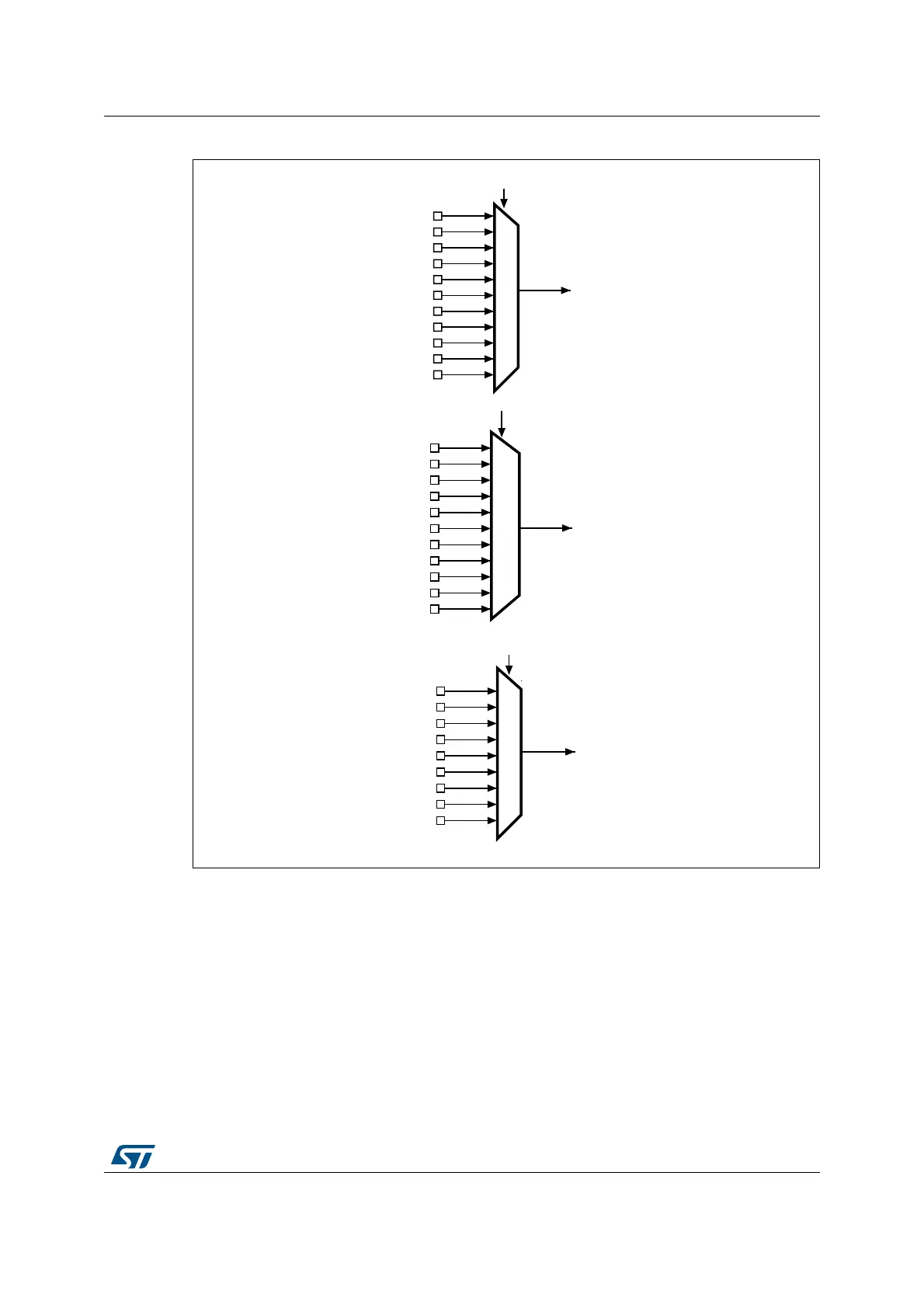
Figure 43. External interrupt/event GPIO mapping (STM32F42xxx and STM32F43xxx)
The seven other EXTI lines are connected as follows:
• EXTI line 16 is connected to the PVD output
• EXTI line 17 is connected to the RTC Alarm event
• EXTI line 18 is connected to the USB OTG FS Wakeup event
• EXTI line 19 is connected to the Ethernet Wakeup event
• EXTI line 20 is connected to the USB OTG HS (configured in FS) Wakeup event
• EXTI line 21 is connected to the RTC Tamper and TimeStamp events
• EXTI line 22 is connected to the RTC Wakeup event
PA0
PB0
PC0
PD0
PE0
PF0
PG0
PH0
PI0
PA1
PB1
PC1
PD1
PE1
PF1
PG1
PH1
PI1
PA15
PB15
PC15
PD15
PE15
PF15
PG15
PH15
EXTI0
EXTI1
EXTI15
EXTI15[3:0] bits in the SYSCFG_EXTICR4 register
EXTI1[3:0] bits in the SYSCFG_EXTICR1 register
EXTI0[3:0] bits in the SYSCFG_EXTICR1 register
MS30440V1
PJ0
PK0
PJ1
PK1
PJ15