RM0090 Rev 18 623/1749
RM0090 General-purpose timers (TIM2 to TIM5)
649
you want in the timer counters. The timers can easily be reset by software using the UG bit
in the TIMx_EGR registers.
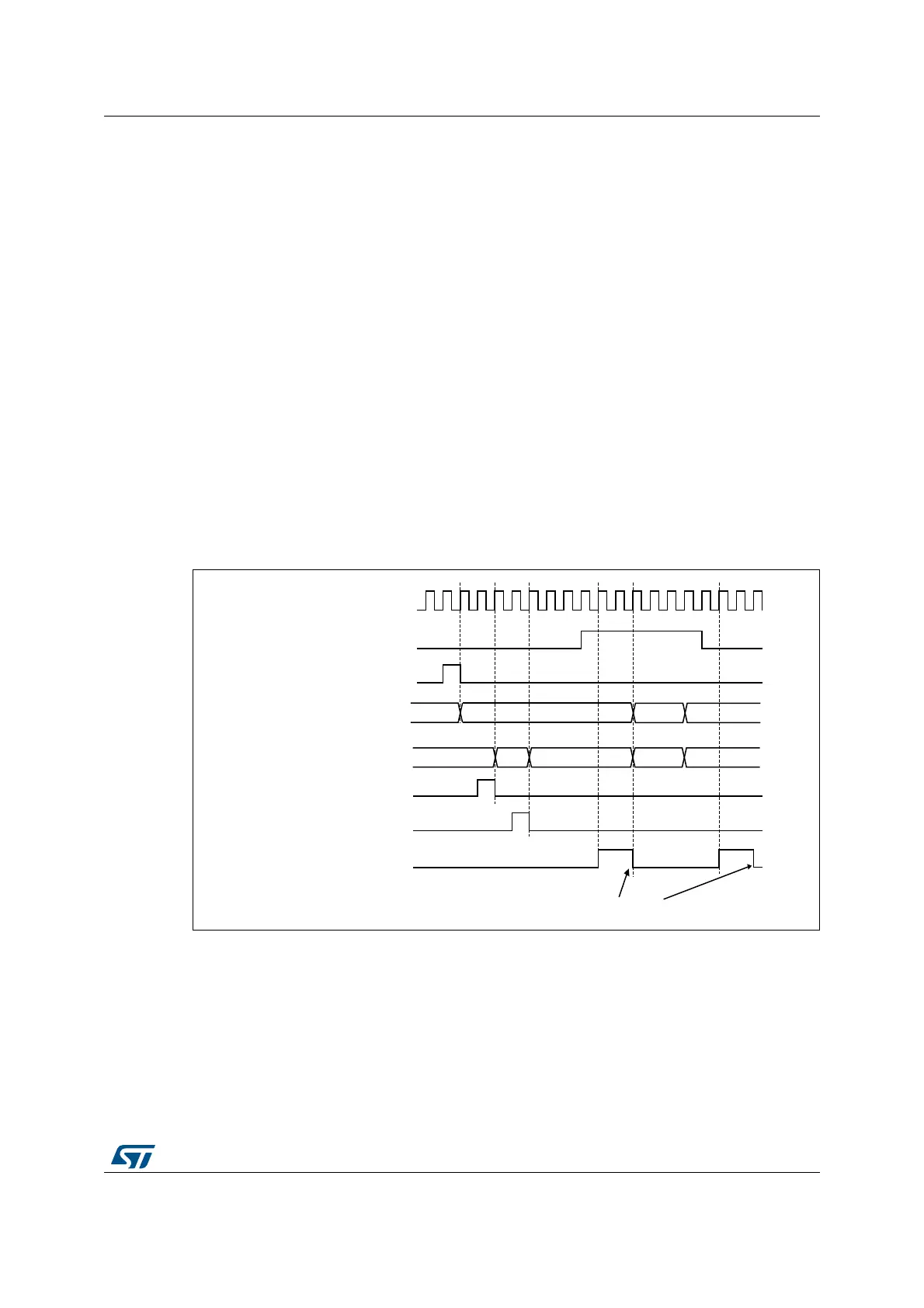
In the next example, we synchronize Timer 1 and Timer 2. Timer 1 is the master and starts
from 0. Timer 2 is the slave and starts from 0xE7. The prescaler ratio is the same for both
timers. Timer 2 stops when Timer 1 is disabled by writing ‘0 to the CEN bit in the TIM1_CR1
register:
• Configure Timer 1 master mode to send its Output Compare 1 Reference (OC1REF)
signal as trigger output (MMS=100 in the TIM1_CR2 register).
• Configure the Timer 1 OC1REF waveform (TIM1_CCMR1 register).
• Configure Timer 2 to get the input trigger from Timer 1 (TS=000 in the TIM2_SMCR
register).
• Configure Timer 2 in gated mode (SMS=101 in TIM2_SMCR register).
• Reset Timer 1 by writing ‘1 in UG bit (TIM1_EGR register).
• Reset Timer 2 by writing ‘1 in UG bit (TIM2_EGR register).
• Initialize Timer 2 to 0xE7 by writing ‘0xE7’ in the timer 2 counter (TIM2_CNTL).
• Enable Timer 2 by writing ‘1 in the CEN bit (TIM2_CR1 register).
• Start Timer 1 by writing ‘1 in the CEN bit (TIM1_CR1 register).
• Stop Timer 1 by writing ‘0 in the CEN bit (TIM1_CR1 register).
Figure 176. Gating timer 2 with Enable of timer 1
MS37389V1
CK_INT
75 00
E7
TIMER1-CNT_INIT
TIMER1-CNT
AB
TIMER2-CNT
TIMER2-CNT_INIT
Write TIF = 0
01 02
E9E800
TIMER1-CEN=CNT_EN
TIMER2-write CNT
TIMER2-TIF