General-purpose timers (TIM2 to TIM5) RM0090
604/1749 RM0090 Rev 18
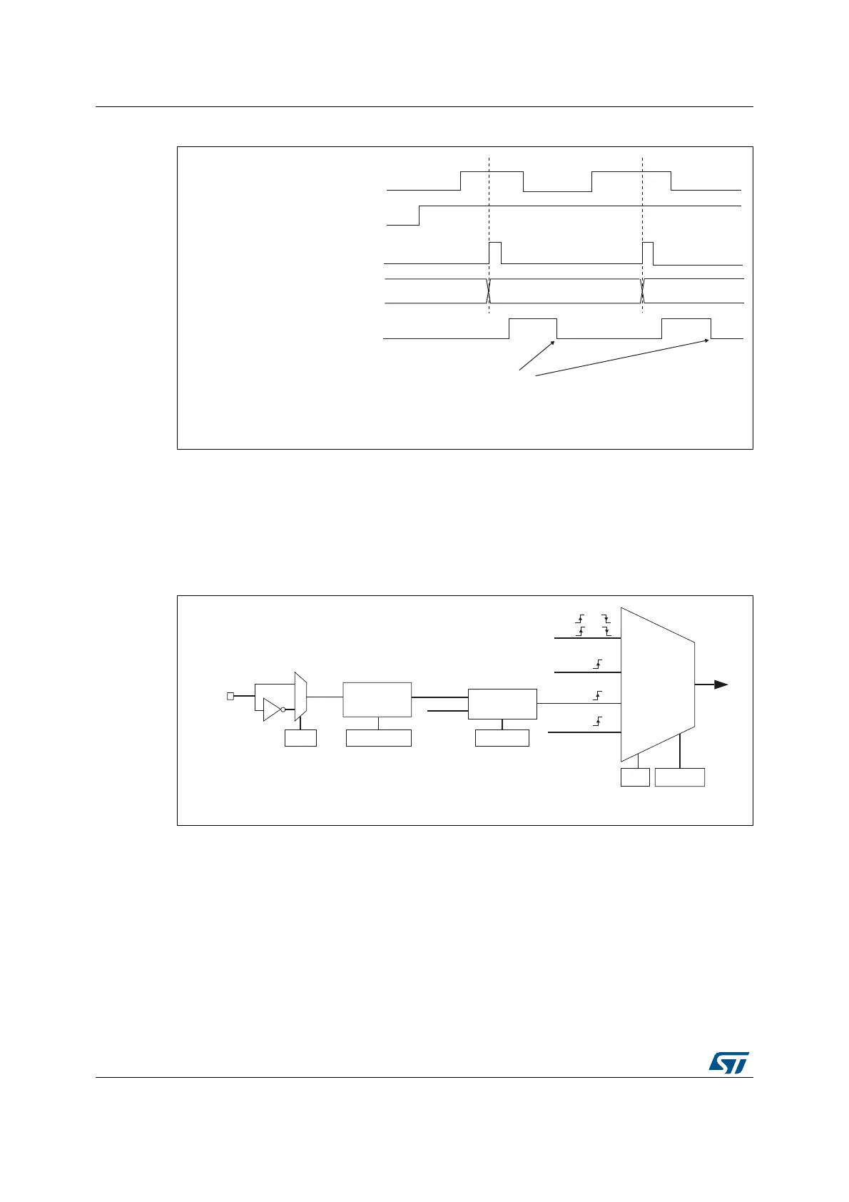
Figure 156. Control circuit in external clock mode 1
External clock source mode 2
This mode is selected by writing ECE=1 in the TIMx_SMCR register.
The counter can count at each rising or falling edge on the external trigger input ETR.
Figure 157 gives an overview of the external trigger input block.
Figure 157. External trigger input block
For example, to configure the upcounter to count each 2 rising edges on ETR, use the
following procedure:
1. As no filter is needed in this example, write ETF[3:0]=0000 in the TIMx_SMCR register.
2. Set the prescaler by writing ETPS[1:0]=01 in the TIMx_SMCR register
3. Select rising edge detection on the ETR pin by writing ETP=0 in the TIMx_SMCR
register
4. Enable external clock mode 2 by writing ECE=1 in the TIMx_SMCR register.
5. Enable the counter by writing CEN=1 in the TIMx_CR1 register.
The counter counts once each 2 ETR rising edges.
Counter clock = CK_CNT = CK_PSC
Counter register
35 3634
TI2
CNT_EN
TIF
Write TIF=0
MS31087V2
MS37365V1
TRGI
CK_INT
TIMx_SMCR
SMS[2:0]
(internal clock)
TI1F or
TI2F or
or
Encoder
mode
ETRF
ECE
0
1
TIMx_SMCR
ETP
ETR pin
ETR
Divider
/1, /2, /4, /8
Filter
downcounter
CK_INT
ETRP
TIMx_SMCR
ETPS[1:0]
TIMx_SMCR
ETF[3:0]
External clock
mode 1
External clock
mode 2
Internal clock
mode
CK_PSC