General-purpose timers (TIM9 to TIM14) RM0090
670/1749 RM0090 Rev 18
Figure 201. Control circuit in gated mode
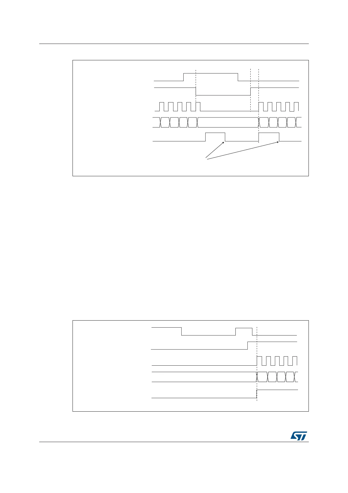
Slave mode: Trigger mode
The counter can start in response to an event on a selected input.
In the following example, the upcounter starts in response to a rising edge on TI2 input:
1. Configure the channel 2 to detect rising edges on TI2. Configure the input filter duration
(in this example, we don’t need any filter, so we keep IC2F=’0000’). The capture
prescaler is not used for triggering, so there’s no need to configure it. The CC2S bits
are configured to select the input capture source only, CC2S=’01’ in TIMx_CCMR1
register. Program CC2P=’1’ and CC2NP=’0’ in TIMx_CCER register to validate the
polarity (and detect low level only).
2. Configure the timer in trigger mode by writing SMS=’110’ in TIMx_SMCR register.
Select TI2 as the input source by writing TS=’110’ in TIMx_SMCR register.
When a rising edge occurs on TI2, the counter starts counting on the internal clock and the
TIF flag is set.
The delay between the rising edge on TI2 and the actual start of the counter is due to the
resynchronization circuit on TI2 input.
Figure 202. Control circuit in trigger mode
MS31402V1
TI1
cnt_en
Write TIF=0
37
Counter clock = ck_cnt = ck_psc
Counter register
38
32 33
34
35 36
3130
TIF
MS31403V1
TI2
cnt_en
37
Counter clock = ck_cnt = ck_psc
Counter register
38
34
35 36
TIF