RM0090 Rev 18 841/1749
RM0090 Inter-integrated circuit (I2C) interface
872
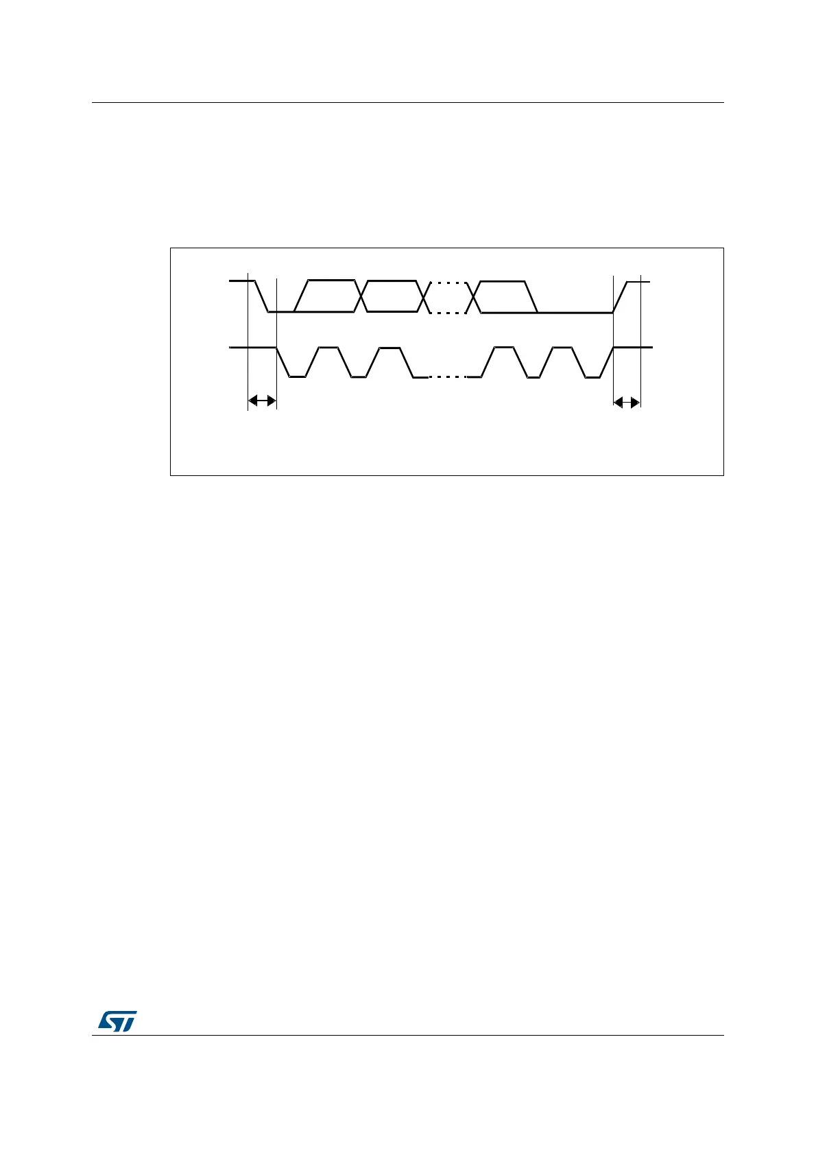
Data and addresses are transferred as 8-bit bytes, MSB first. The first byte(s) following the
start condition contain the address (one in 7-bit mode, two in 10-bit mode). The address is
always transmitted in Master mode.
A 9th clock pulse follows the 8 clock cycles of a byte transfer, during which the receiver must
send an acknowledge bit to the transmitter. Refer to Figure 238.
Figure 238. I
2
C bus protocol
Acknowledge may be enabled or disabled by software. The I
2
C interface addresses (dual
addressing 7-bit/ 10-bit and/or general call address) can be selected by software.
The block diagram of the I
2
C interface is shown in Figure 239.
MS19854V1
SDA
SCL
Start
condition
Stop
condition
MSB ACK
12 89