RM0090 Rev 18 455/1749
RM0090 Digital camera interface (DCMI)
479
15 Digital camera interface (DCMI)
This section applies to all STM32F4xx devices, unless otherwise specified.
15.1 DCMI introduction
The digital camera is a synchronous parallel interface able to receive a high-speed data flow
from an external 8-, 10-, 12- or 14-bit CMOS camera module. It supports different data
formats: YCbCr4:2:2/RGB565 progressive video and compressed data (JPEG).
This interface is for use with black & white cameras, X24 and X5 cameras, and it is
assumed that all pre-processing like resizing is performed in the camera module.
15.2 DCMI main features
• 8-, 10-, 12- or 14-bit parallel interface
• Embedded/external line and frame synchronization
• Continuous or snapshot mode
• Crop feature
• Supports the following data formats:
– 8/10/12/14- bit progressive video: either monochrome or raw bayer
– YCbCr 4:2:2 progressive video
– RGB 565 progressive video
– Compressed data: JPEG
15.3 DCMI pins
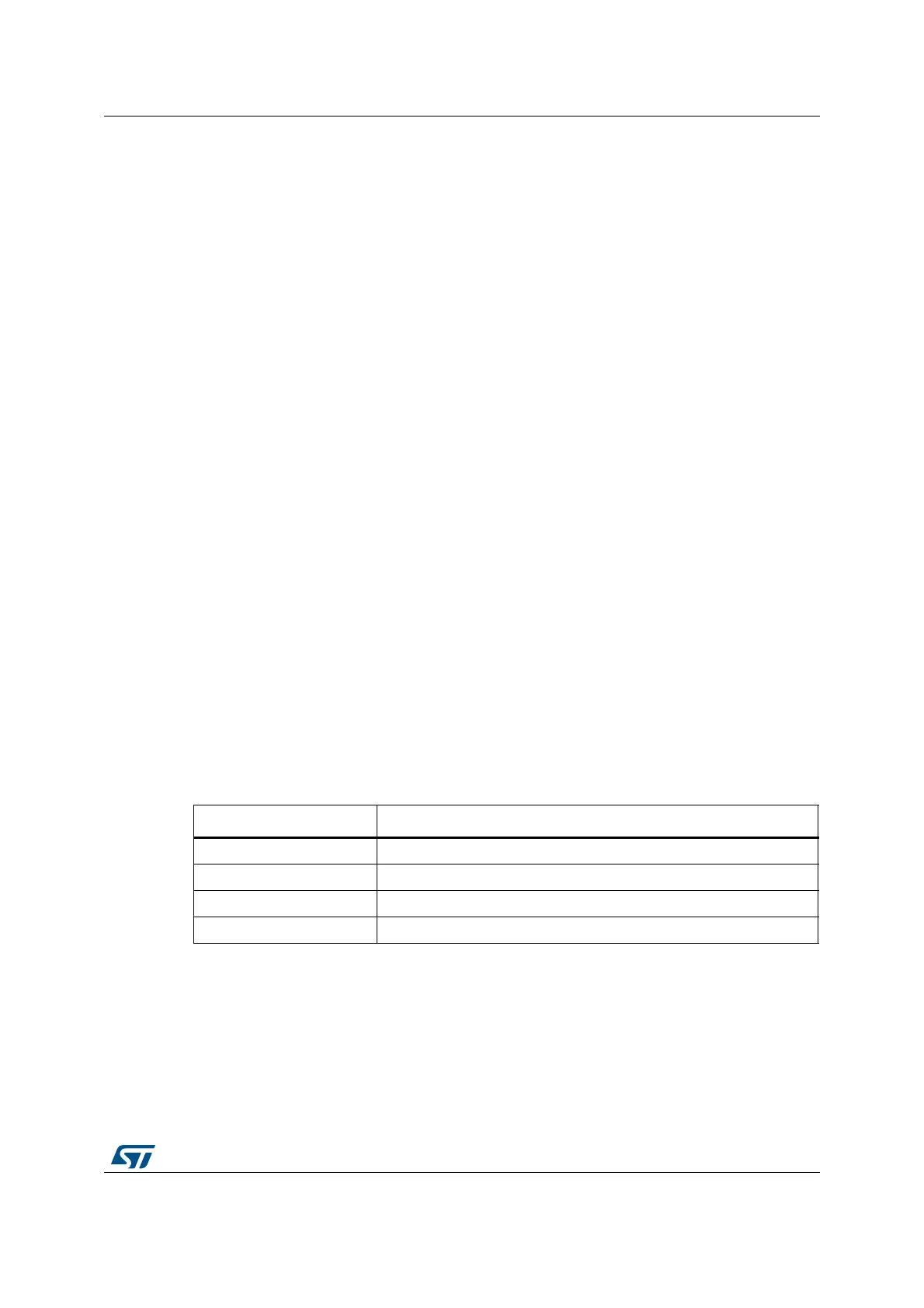
Table 77 shows the DCMI pins.
15.4 DCMI clocks
The digital camera interface uses two clock domains PIXCLK and HCLK. The signals
generated with PIXCLK are sampled on the rising edge of HCLK once they are stable. An
enable signal is generated in the HCLK domain, to indicate that data coming from the
camera are stable and can be sampled. The minimum PIXCLK period must be higher than
2.5 HCLK periods.
Table 77. DCMI pins
Name Signal type
D[0:13] Data inputs
HSYNC Horizontal synchronization input
VSYNC Vertical synchronization input
PIXCLK Pixel clock input