RM0090 Rev 18 995/1749
RM0090 Universal synchronous asynchronous receiver transmitter (USART)
1018
has been written). This means that it is not possible to receive a synchronous data without
transmitting data.
The LBCL, CPOL and CPHA bits have to be selected when both the transmitter and the
receiver are disabled (TE=RE=0) to ensure that the clock pulses function correctly. These
bits should not be changed while the transmitter or the receiver is enabled.
It is advised that TE and RE are set in the same instruction in order to minimize the setup
and the hold time of the receiver.
The USART supports master mode only: it cannot receive or send data related to an input
clock (CK is always an output).
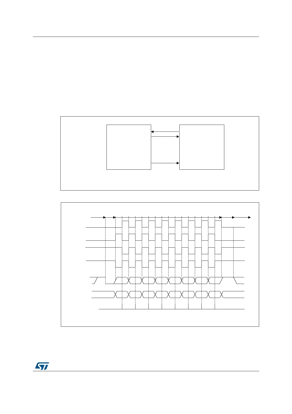
Figure 307. USART example of synchronous transmission
Figure 308. USART data clock timing diagram (M=0)
MSv31158V2
USART
Synchronous device
(e.g. slave SPI)
RX
TX
Data out
Data in
Clock
CK
MSv31159V1
0 1 2 3 4 5 6 7
0 1 2 3 4 5 6 7
*
*
*
*
MSB
MSB
LSB
LSB
Start
Start Stop
Idle or preceding
transmission
Idle or next
transmission
*
*LBCL bit controls last data pulse
Capture strobe
Data on RX
(from slave)
Data on TX
(from master)
Clock (CPOL=1, CPHA=1
Clock (CPOL=1, CPHA=0
Clock (CPOL=0, CPHA=1
Clock (CPOL=0, CPHA=0
Stop
M=0 (8 data bits)