RM0090 Rev 18 881/1749
RM0090 Serial peripheral interface (SPI)
925
After the last sampling clock edge the RXNE bit is set, a copy of the data byte received in
the shift register is moved to the Rx buffer. When the SPI_DR register is read, the SPI
peripheral returns this buffered value.
Clearing of the RXNE bit is performed by reading the SPI_DR register.
SPI TI protocol in slave mode
In slave mode, the SPI interface is compatible with the TI protocol. The FRF bit of the
SPI_CR2 register can be used to configure the slave SPI serial communications to be
compliant with this protocol.
The clock polarity and phase are forced to conform to the TI protocol requirements whatever
the values set in the SPI_CR1 register. NSS management is also specific to the TI protocol
which makes the configuration of NSS management through the SPI_CR1 and SPI_CR2
registers (such as SSM, SSI, SSOE) transparent for the user.
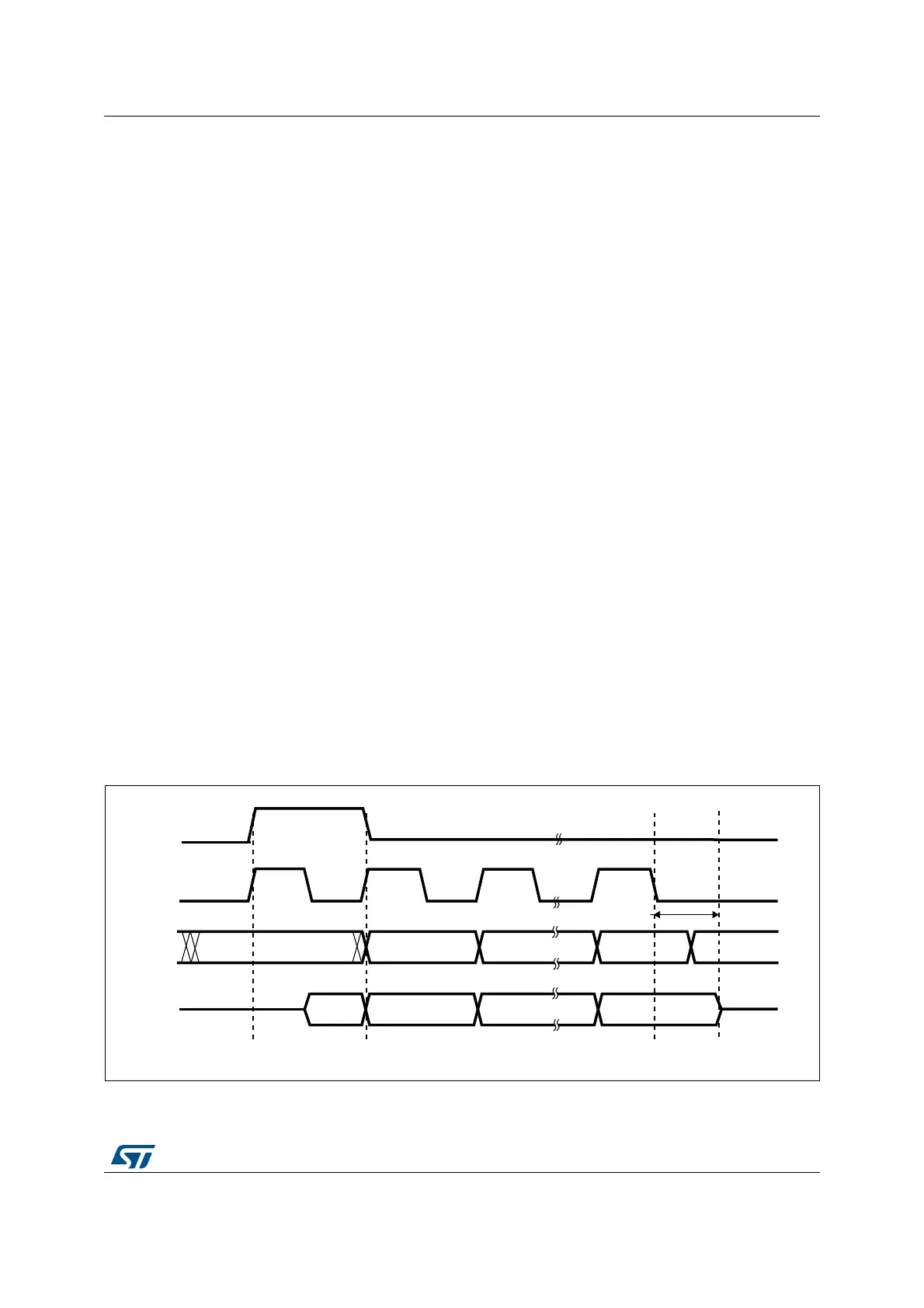
In Slave mode (Figure 249: TI mode - Slave mode, single transfer and Figure 250: TI mode
- Slave mode, continuous transfer), the SPI baud rate prescaler is used to control the
moment when the MISO pin state changes to HI-Z. Any baud rate can be used thus allowing
to determine this moment with optimal flexibility. However, the baud rate is generally set to
the external master clock baud rate. The time for the MISO signal to become HI-Z (t
release
)
depends on internal resynchronizations and on the baud rate value set in through BR[2:0] of
SPI_CR1 register. It is given by the formula:
Note: This feature is not available for Motorola SPI communications (FRF bit set to 0).
To detect TI frame errors in Slave transmitter only mode by using the Error interrupt (ERRIE
= 1), the SPI must be configured in 2-line unidirectional mode by setting BIDIMODE and
BIDIOE to 1 in the SPI_CR1 register. When BIDIMODE is set to 0, OVR is set to 1 because
the data register is never read and error interrupt are always generated, while when
BIDIMODE is set to 1, data are not received and OVR is never set.
Figure 249. TI mode - Slave mode, single transfer
t
baud_rate
2
----------------------------
4t
pclk
×+ t
release
t
baud_rate
2
----------------------------
6t
pclk
×+<<
ai18434
MSBIN
MOSI
input
NSS
input
SCK
input
trigger
edge
sampling
edge
trigger
edge
sampling
edge
trigger
edge
sampling
edge
DONTCARE LSBIN DONTCARE
MISO
output
1 or 0 MSBOUT
LSBOUT
t
Release