General-purpose timers (TIM2 to TIM5) RM0090
624/1749 RM0090 Rev 18
Using one timer to start another timer
In this example, we set the enable of Timer 2 with the update event of Timer 1. Refer to
Figure 174 for connections. Timer 2 starts counting from its current value (which can be
nonzero) on the divided internal clock as soon as the update event is generated by Timer 1.
When Timer 2 receives the trigger signal its CEN bit is automatically set and the counter
counts until we write ‘0 to the CEN bit in the TIM2_CR1 register. Both counter clock
frequencies are divided by 3 by the prescaler compared to CK_INT (f
CK_CNT
= f
CK_INT
/3).
• Configure Timer 1 master mode to send its Update Event (UEV) as trigger output
(MMS=010 in the TIM1_CR2 register).
• Configure the Timer 1 period (TIM1_ARR registers).
• Configure Timer 2 to get the input trigger from Timer 1 (TS=000 in the TIM2_SMCR
register).
• Configure Timer 2 in trigger mode (SMS=110 in TIM2_SMCR register).
• Start Timer 1 by writing ‘1 in the CEN bit (TIM1_CR1 register).
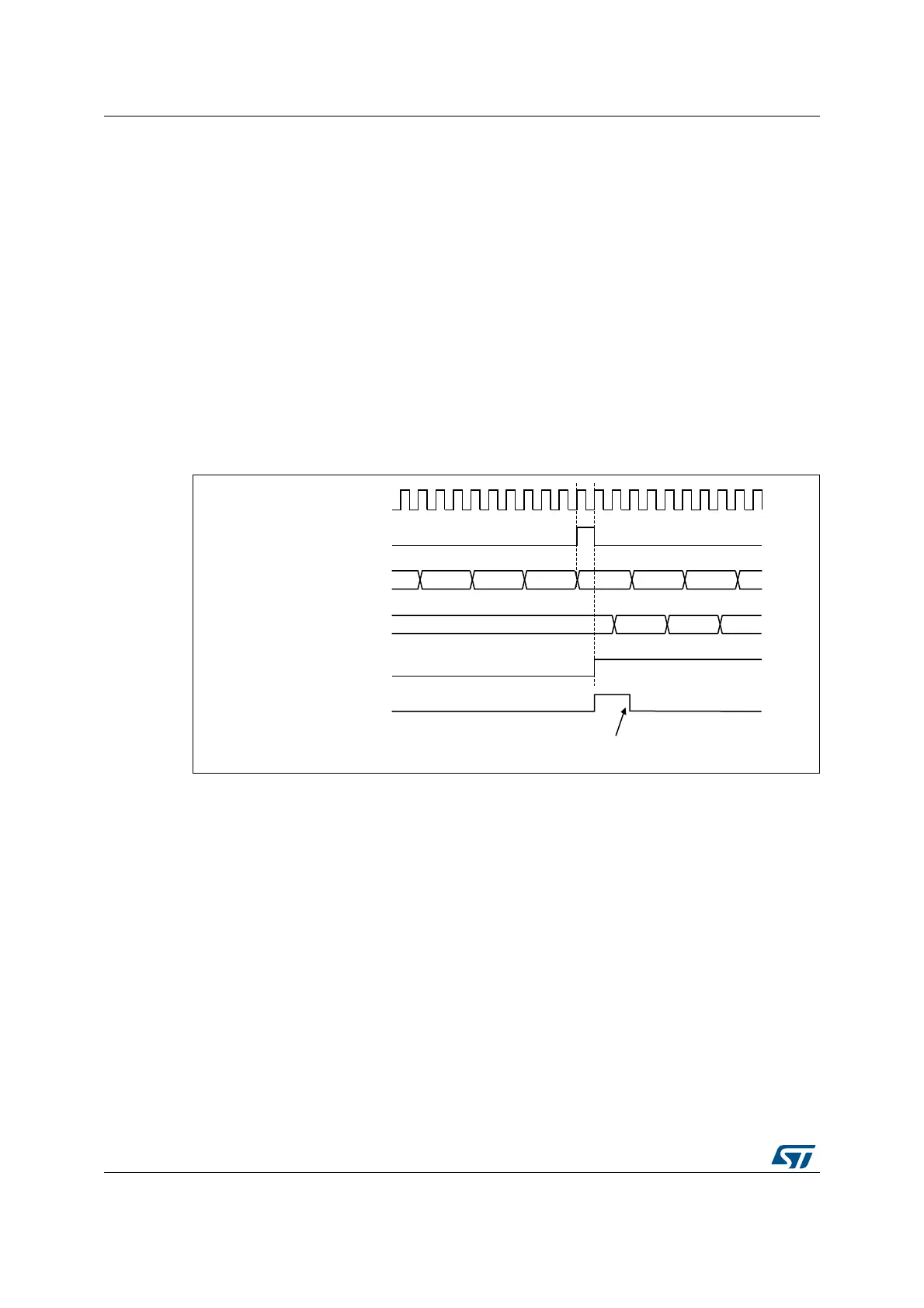
Figure 177. Triggering timer 2 with update of timer 1
As in the previous example, the user can initialize both counters before starting counting.
Figure 178 shows the behavior with the same configuration as in Figure 177 but in trigger
mode instead of gated mode (SMS=110 in the TIM2_SMCR register).
MS37390V1
Write TIF = 0
CK_INT
TIMER2-CNT
FD
TIMER1-CNT
TIMER2-CEN=CNT_EN
TIMER2-TIF
FE FF 00 01 02
46 47 4845
TIMER1-UEV