RM0090 Rev 18 907/1749
RM0090 Serial peripheral interface (SPI)
925
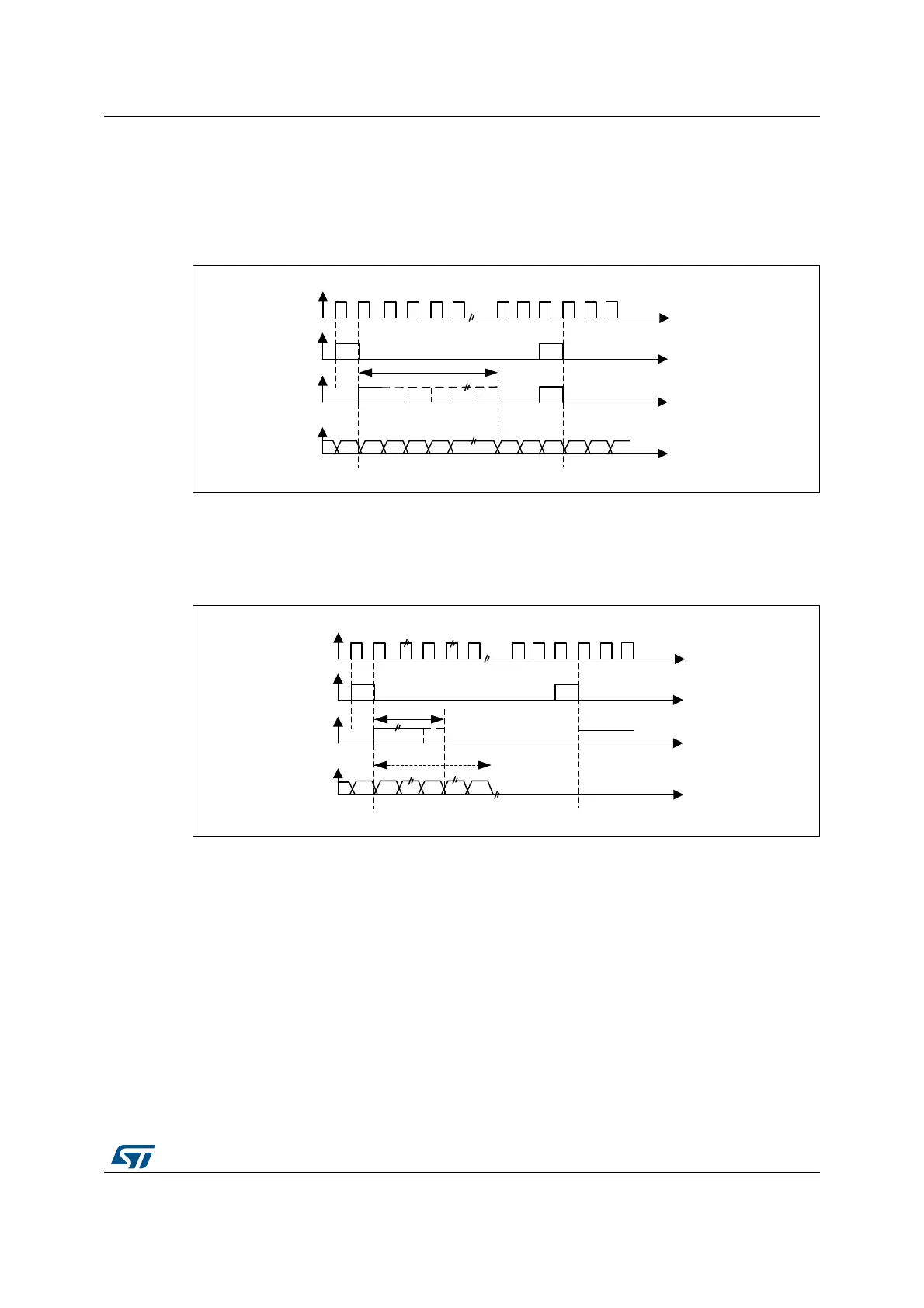
PCM standard
For the PCM standard, there is no need to use channel-side information. The two PCM
modes (short and long frame) are available and configurable using the PCMSYNC bit in
SPI_I2SCFGR.
Figure 279. PCM standard waveforms (16-bit)
For long frame synchronization, the WS signal assertion time is fixed 13 bits in master
mode.
For short frame synchronization, the WS synchronization signal is only one cycle long.
Figure 280. PCM standard waveforms (16-bit extended to 32-bit packet frame)
Note: For both modes (master and slave) and for both synchronizations (short and long), the
number of bits between two consecutive pieces of data (and so two synchronization signals)
needs to be specified (DATLEN and CHLEN bits in the SPI_I2SCFGR register) even in
slave mode.
28.4.4 Clock generator
The I
2
S bitrate determines the dataflow on the I
2
S data line and the I
2
S clock signal
frequency.
I
2
S bitrate = number of bits per channel × number of channels × sampling audio frequency
For a 16-bit audio, left and right channel, the I
2
S bitrate is calculated as follows:
I
2
S bitrate = 16 × 2 × F
S
It will be: I
2
S bitrate = 32 x 2 x F
S
if the packet length is 32-bit wide.
MS30106V1
CK
WS
short frame
SD
WS
long frame
13-bits
MSB
LSB
MSB
MS30107V1
CK
WS
short frame
SD
WS
long frame
Up to 13-bits
MSB
LSB
16 bits