RM0090 Rev 18 939/1749
RM0090 Serial audio interface (SAI)
964
29.11 AC’97 link controller
The SAI is able to work as an AC’97 link controller. In this protocol:
• The slot number and the slot size are fixed.
• The frame synchronization signal is perfectly defined and has a fixed shape.
To select this protocol, set bit PRTCFG[1:0] in the SAI_xCR1 register to 10. When AC’97
mode is selected the data sizes that can be used are 16-bit or 20-bit only, else SAI behavior
is not guaranteed.
• Bits NBSLOT[3:0] and SLOTSZ[1:0] are consequently ignored.
• The number of slots is fixed at 13 slots. The first one is 16 bits wide and all the others
are 20 bits wide (data slots).
• Bit FBOFF[5:0] in the SAI_xSLOTR register is ignored
• The SAI_xFRCR register is ignored.
The FS signal from the block defined as asynchronous is configured automatically as an
output, since the AC’97 controller link drives the FS signal whatever the master or slave
configuration.
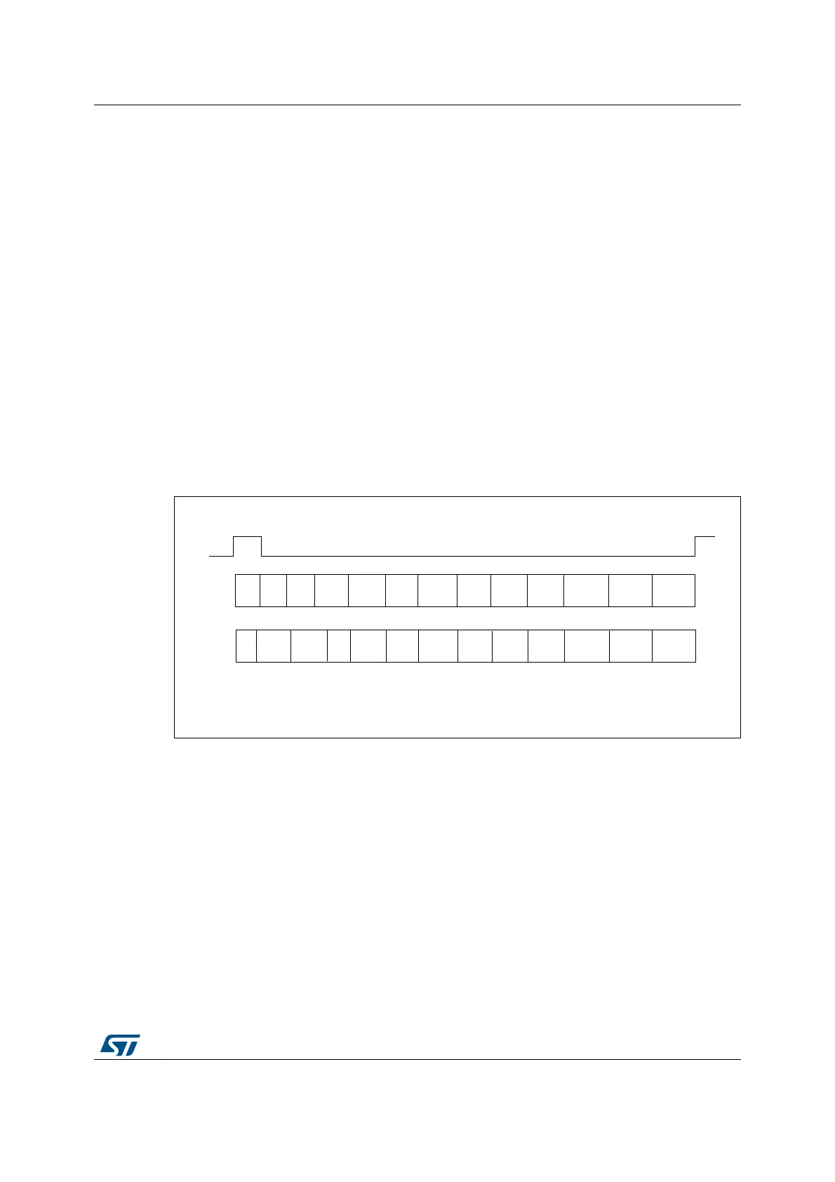
Figure 290 presents an AC’97 audio frame structure.
Figure 290. AC’97 audio frame
Note: In AC’97 protocol, bit 2 of the tag is reserved (always 0), so whatever the value written in the
SAI FIFO, bit 2 of the TAG is forced to 0 level.
For more details about TAG representation, please refer to the AC’97 protocol standard.
One SAI can be used to target an AC’97 point-to-point communication.
In receiver mode, the SAI acting as an AC’97 link controller will require no FIFO request and
so no data storage in the FIFO when the codec ready bit in the slot 0 is decoded low. If bit
CNRDYIE is enabled in the SAI_xIM register, flag CNRDY will be set in the SAI_xSR
register and an interrupt is generated. This flag is dedicated to the AC’97 protocol.
MS192343V1
FS
123 4 5 6 7 8 9 10 1112
SDI
SDO
Tag
CMD
ADDR
CMD
DATA
LINE1
DAC
PCM
LFRONT
PCM
RFRONT
PCM
CENTER
PCM
LSURR
PCM
RSURR
PCM
LFE
LINE2
DAC
HSET
DAC
IO
CTRL
Tag
STATUS
ADDR
STATUS
DATA
LINE1
ADC
PCM
LEFT
PCM
RIGHT
PCM
MIC
RSR
VD
RSR
LVD
LINE2
ADC
HSET
IO
STATUS
RSR
VD