Debug support (DBG) RM0090
1708/1749 RM0090 Rev 18
38.17.2 TRACE pin assignment
• Asynchronous mode
The asynchronous mode requires 1 extra pin and is available on all packages. It is only
available if using Serial Wire mode (not in JTAG mode).
• Synchronous mode
The synchronous mode requires from 2 to 6 extra pins depending on the data trace
size and is only available in the larger packages. In addition it is available in JTAG
mode and in Serial Wire mode and provides better bandwidth output capabilities than
asynchronous trace.
TPUI TRACE pin assignment
By default, these pins are NOT assigned. They can be assigned by setting the
TRACE_IOEN and TRACE_MODE bits in the MCU Debug component configuration
register. This configuration has to be done by the debugger host.
In addition, the number of pins to assign depends on the trace configuration (asynchronous
or synchronous).
• Asynchronous mode: 1 extra pin is needed
• Synchronous mode: from 2 to 5 extra pins are needed depending on the size of the
data trace port register (1, 2 or 4):
– TRACECK
– TRACED(0) if port size is configured to 1, 2 or 4
– TRACED(1) if port size is configured to 2 or 4
– TRACED(2) if port size is configured to 4
– TRACED(3) if port size is configured to 4
To assign the TRACE pin, the debugger host must program the bits TRACE_IOEN and
TRACE_MODE[1:0] of the Debug MCU configuration Register (DBGMCU_CR). By default
the TRACE pins are not assigned.
This register is mapped on the external PPB and is reset by the PORESET (and not by the
SYSTEM reset). It can be written by the debugger under SYSTEM reset.
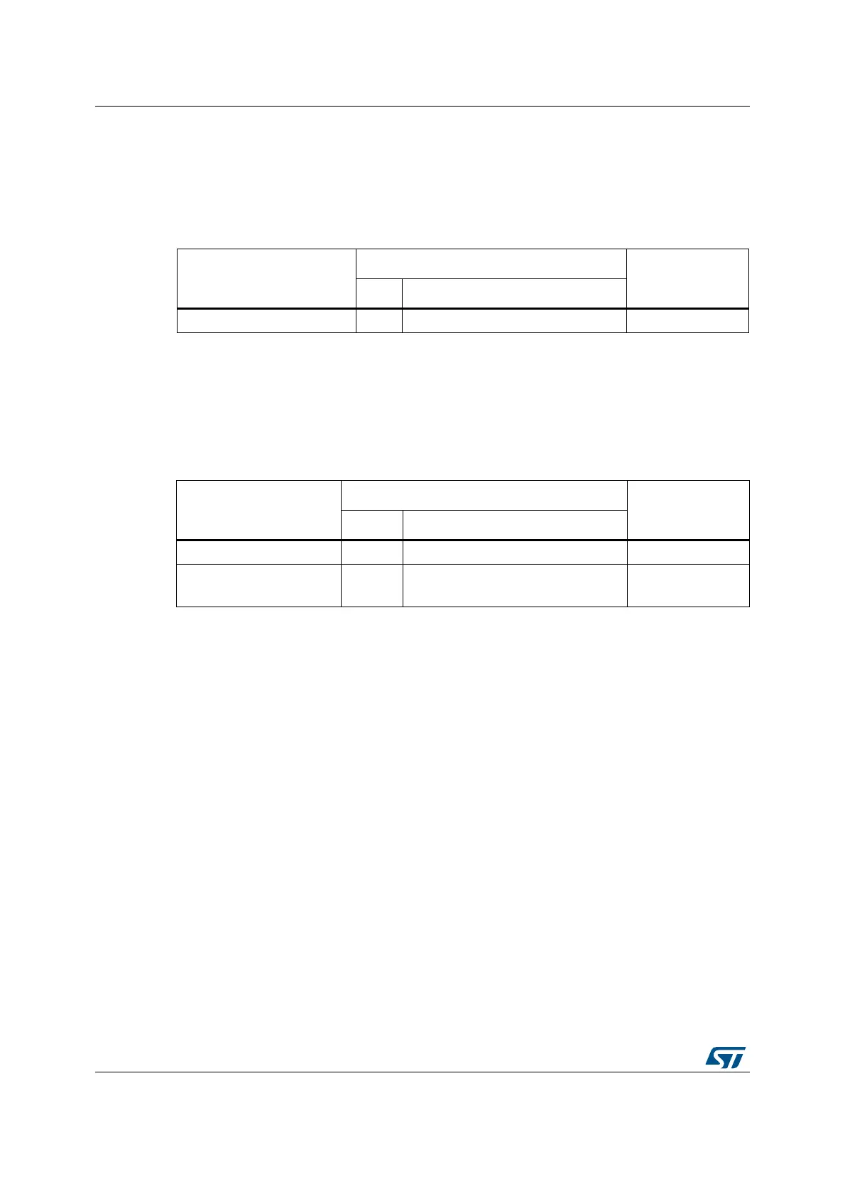
Table 310. Asynchronous TRACE pin assignment
TPUI pin name
Trace synchronous mode
STM32F4xx pin
assignment
Type Description
TRACESWO O TRACE Async Data Output PB3
Table 311. Synchronous TRACE pin assignment
TPUI pin name
Trace synchronous mode
STM32F4xxpin
assignment
Type Description
TRACECK O TRACE Clock PE2
TRACED[3:0] O
TRACE Sync Data Outputs
Can be 1, 2 or 4.
PE[6:3]