General-purpose timers (TIM9 to TIM14) RM0090
666/1749 RM0090 Rev 18
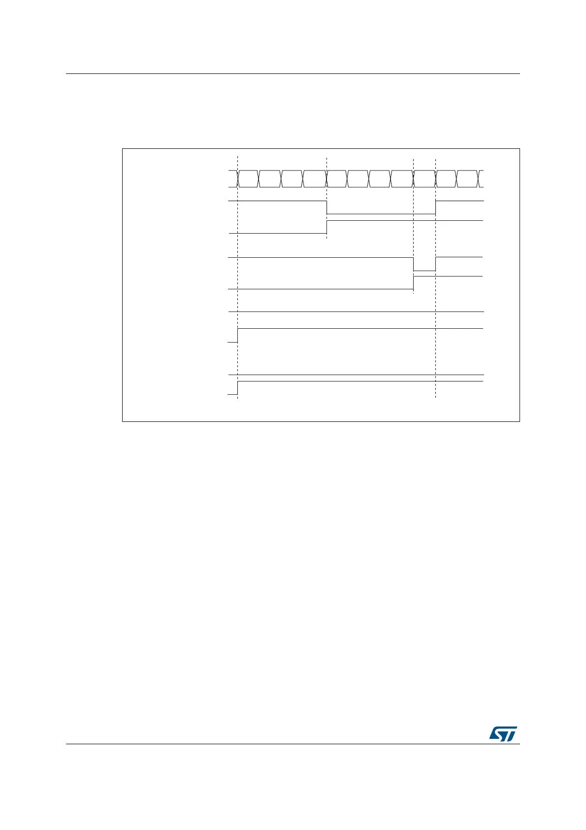
TIMx_CCRx is greater than the auto-reload value (in TIMx_ARR) then OCxREF is held at
‘1’. If the compare value is 0 then OCxRef is held at ‘0’. Figure 198 shows some edge-
aligned PWM waveforms in an example where TIMx_ARR=8.
Figure 198. Edge-aligned PWM waveforms (ARR=8)
19.3.10 One-pulse mode
One-pulse mode (OPM) is a particular case of the previous modes. It allows the counter to
be started in response to a stimulus and to generate a pulse with a programmable length
after a programmable delay.
Starting the counter can be controlled through the slave mode controller. Generating the
waveform can be done in output compare mode or PWM mode. Select One-pulse mode by
setting the OPM bit in the TIMx_CR1 register. This makes the counter stop automatically at
the next update event UEV.
A pulse can be correctly generated only if the compare value is different from the counter
initial value. Before starting (when the timer is waiting for the trigger), the configuration must
be as follows:
CNT < CCRx≤ ARR (in particular, 0 < CCRx)
MS31093V1
Counter register
‘1’
0
12 3456 7801
OCXREF
CCxIF
OCXREF
CCxIF
OCXREF
CCxIF
OCXREF
CCxIF
CCRx=4
CCRx=8
CCRx>8
CCRx=0
‘0’