RM0090 Rev 18 125/1749
RM0090 Power controller (PWR)
149
5.2.2 Brownout reset (BOR)
During power on, the Brownout reset (BOR) keeps the device under reset until the supply
voltage reaches the specified V
BOR
threshold.
V
BOR
is configured through device option bytes. By default, BOR is off. 3 programmable
V
BOR
threshold levels can be selected:
• BOR Level 3 (VBOR3). Brownout threshold level 3.
• BOR Level 2 (VBOR2). Brownout threshold level 2.
• BOR Level 1 (VBOR1). Brownout threshold level 1.
Note: For full details about BOR characteristics, refer to the "Electrical characteristics" section in
the device datasheet.
When the supply voltage (V
DD
) drops below the selected V
BOR
threshold, a device reset is
generated.
The BOR can be disabled by programming the device option bytes. In this case, the
power-on and power-down is then monitored by the POR/ PDR (see Section 5.2.1: Power-
on reset (POR)/power-down reset (PDR)).
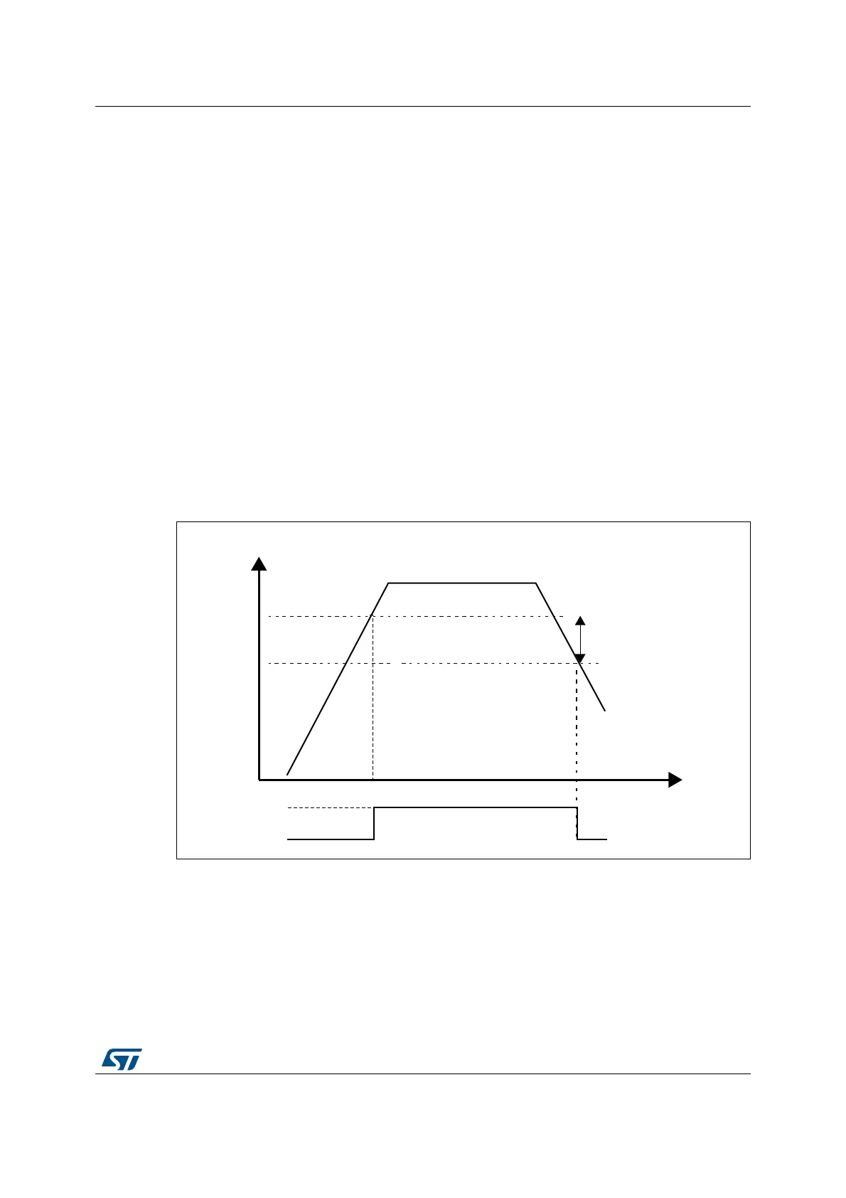
The BOR threshold hysteresis is ~100 mV (between the rising and the falling edge of the
supply voltage).
Figure 13. BOR thresholds
5.2.3 Programmable voltage detector (PVD)
You can use the PVD to monitor the V
DD
power supply by comparing it to a threshold
selected by the PLS[2:0] bits in the PWR power control register (PWR_CR) for
MS30433V1
VDD/VDDA
100 mV
hysteresis
BOR threshold
Reset