RM0090 Rev 18 365/1749
RM0090 Chrom-Art Accelerator™ controller (DMA2D)
370
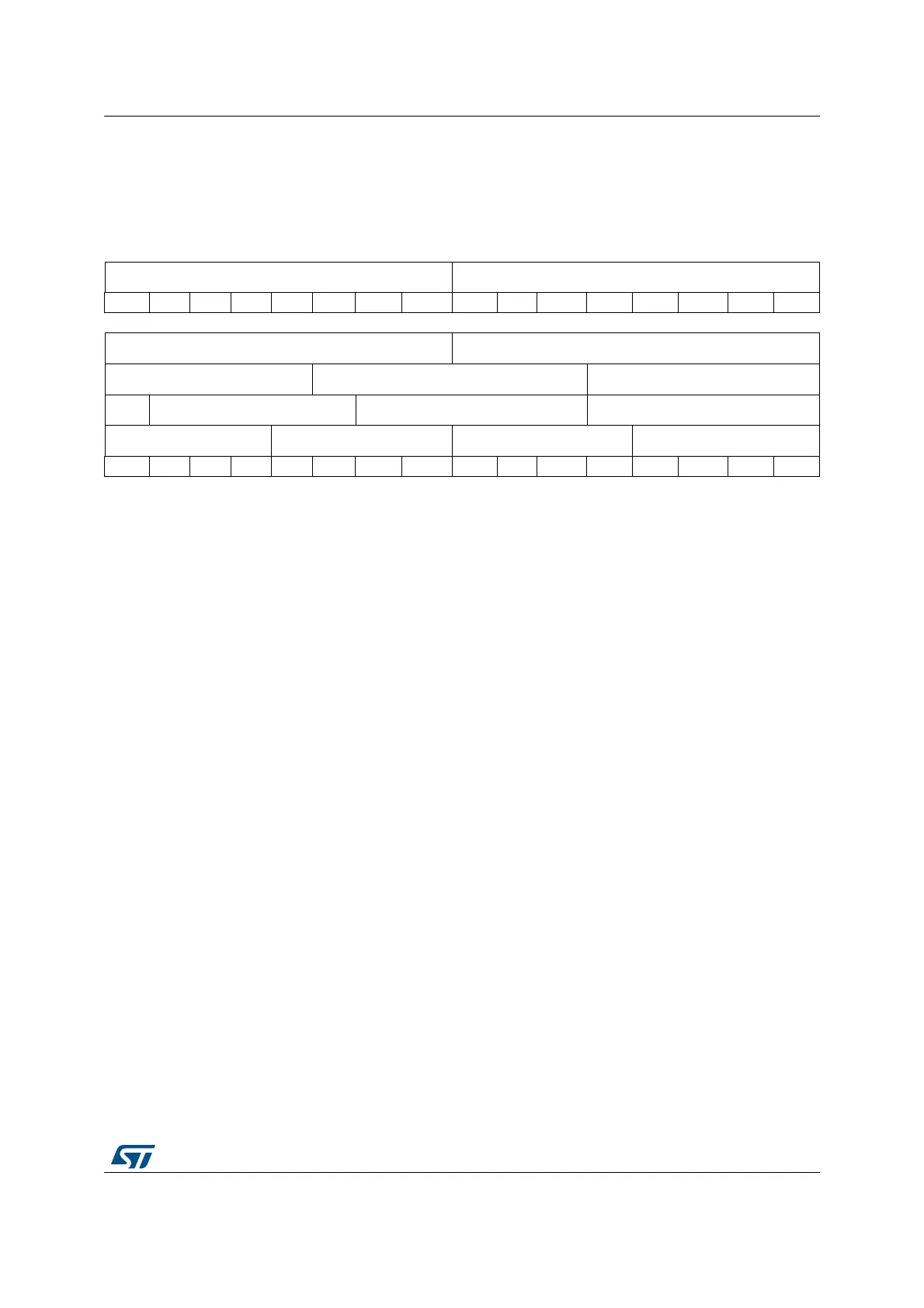
11.5.15 DMA2D output color register (DMA2D_OCOLR)
Address offset: 0x0038
Reset value: 0x0000 0000
31 30 29 28 27 26 25 24 23 22 21 20 19 18 17 16
ALPHA[7:0] RED[7:0]
rw rw rw rw rw rw rw rw rw rw rw rw rw rw rw rw
15 14 13 12 11 10 9 8 7 6 5 4 3 2 1 0
GREEN[7:0] BLUE[7:0]
RED[4:0] GREEN[5:0] BLUE[4:0]
A RED[4:0] GREEN[4:0] BLUE[4:0]
ALPHA[3:0] RED[3:0] GREEN[3:0] BLUE[3:0]
rw rw rw rw rw rw rw rw rw rw rw rw rw rw rw rw
Bits 31:24 ALPHA[7: 0]: Alpha Channel Value
These bits define the alpha channel of the output color. These bits can only be written
when data transfers are disabled. Once the transfer has started, they are read-only.
Bits 23:16 RED[7: 0]: Red Value
These bits define the red value of the output image. These bits can only be written when
data transfers are disabled. Once the transfer has started, they are read-only.
Bits 15:8 GREEN[7: 0]: Green Value
These bits define the green value of the output image. These bits can only be written
when data transfers are disabled. Once the transfer has started, they are read-only.
Bits 7:0 BLUE[7: 0]: Blue Value
These bits define the blue value of the output image. These bits can only be written
when data transfers are disabled. Once the transfer has started, they are read-only.