RM0090 Rev 18 415/1749
RM0090 Analog-to-digital converter (ADC)
432
13.13 ADC registers
Refer to Section 1.1: List of abbreviations for registers for registers for a list of abbreviations
used in register descriptions.
The peripheral registers must be written at word level (32 bits). Read accesses can be done
by bytes (8 bits), half-words (16 bits) or words (32 bits).
13.13.1 ADC status register (ADC_SR)
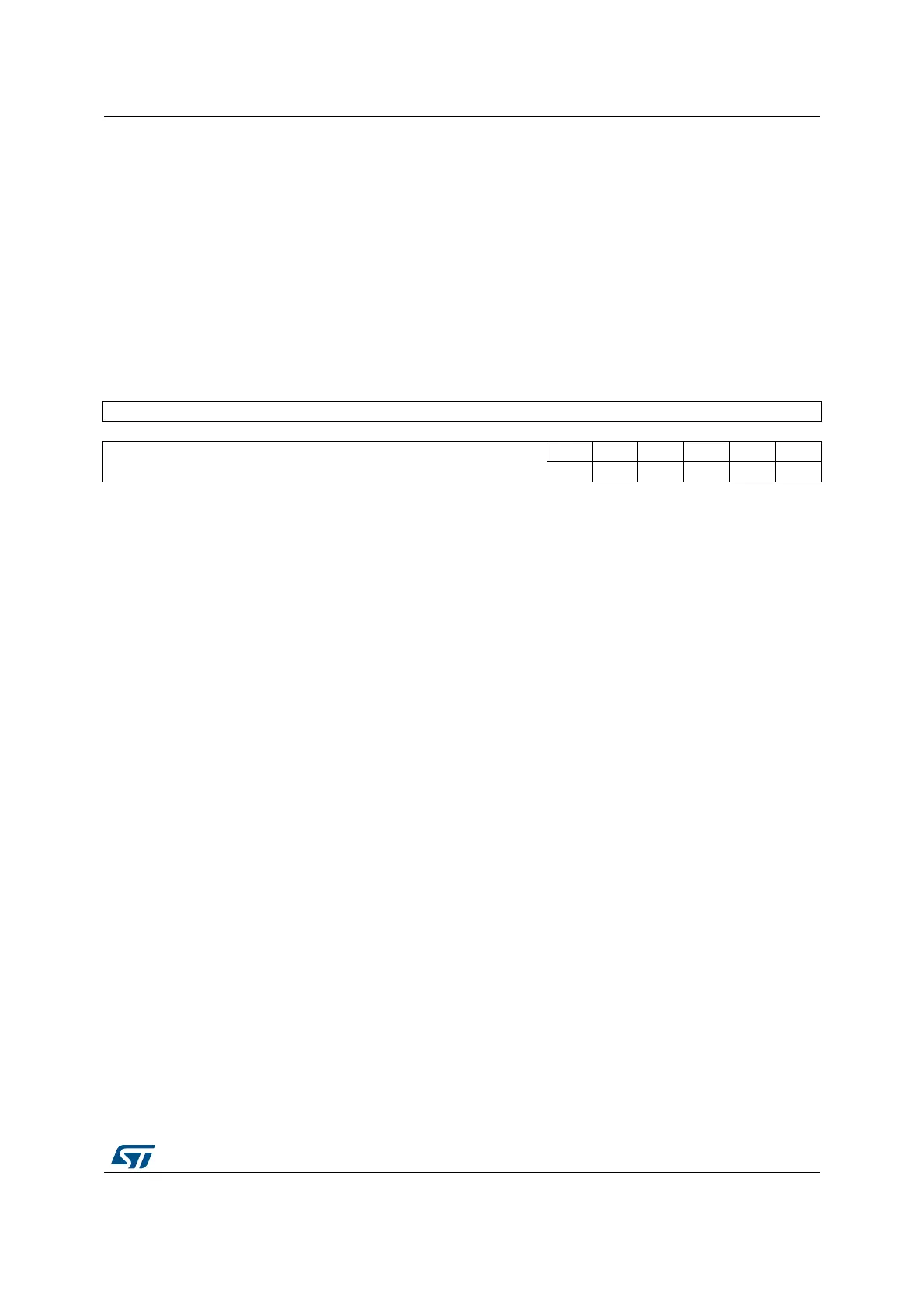
Address offset: 0x00
Reset value: 0x0000 0000
31 30 29 28 27 26 25 24 23 22 21 20 19 18 17 16
Reserved
1514131211109876543210
Reserved
OVR STRT JSTRT JEOC EOC AWD
rc_w0 rc_w0 rc_w0 rc_w0 rc_w0 rc_w0
Bits 31:6 Reserved, must be kept at reset value.
Bit 5 OVR: Overrun
This bit is set by hardware when data are lost (either in single mode or in dual/triple mode). It
is cleared by software. Overrun detection is enabled only when DMA = 1 or EOCS = 1.
0: No overrun occurred
1: Overrun has occurred
Bit 4 STRT: Regular channel start flag
This bit is set by hardware when regular channel conversion starts. It is cleared by software.
0: No regular channel conversion started
1: Regular channel conversion has started
Bit 3 JSTRT: Injected channel start flag
This bit is set by hardware when injected group conversion starts. It is cleared by software.
0: No injected group conversion started
1: Injected group conversion has started
Bit 2 JEOC: Injected channel end of conversion
This bit is set by hardware at the end of the conversion of all injected channels in the group.
It is cleared by software.
0: Conversion is not complete
1: Conversion complete
Bit 1 EOC: Regular channel end of conversion
This bit is set by hardware at the end of the conversion of a regular group of channels. It is
cleared by software or by reading the ADC_DR register.
0: Conversion not complete (EOCS=0), or sequence of conversions not complete (EOCS=1)
1: Conversion complete (EOCS=0), or sequence of conversions complete (EOCS=1)
Bit 0 AWD: Analog watchdog flag
This bit is set by hardware when the converted voltage crosses the values programmed in
the ADC_LTR and ADC_HTR registers. It is cleared by software.
0: No analog watchdog event occurred
1: Analog watchdog event occurred