Real-time clock (RTC) RM0090
832/1749 RM0090 Rev 18
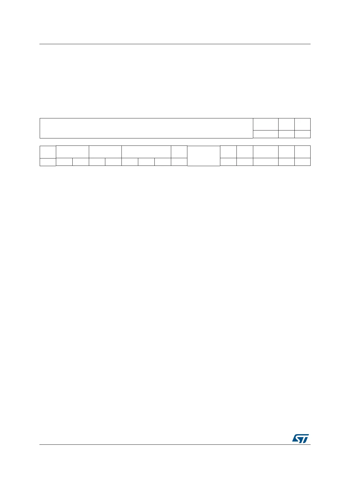
26.6.17 RTC tamper and alternate function configuration register
(RTC_TAFCR)
Address offset: 0x40
Backup domain reset value: 0x0000 0000
System reset: not affected
31 30 29 28 27 26 25 24 23 22 21 20 19 18 17 16
Reserved
ALARMOUT
TYPE
TSIN
SEL
TAMP1
INSEL
rw rw rw
1514131211109876543 2 10
TAMP-
PUDIS
TAMP-
PRCH[1:0]
TAMPFLT[1:0] TAMPFREQ[2:0]
TAMPT
S
Reserved
TAMP2
-TRG
TAMP2
E
TAMPIE
TAMP1
TRG
TAMP1
E
rw rw rw rw rw rw rw rw rw rw rw rw rw rw
Bits 31:19 Reserved. Always read as 0.
Bit 18 ALARMOUTTYPE: RTC_ALARM output type
0: RTC_ALARM is an open-drain output
1: RTC_ALARM is a push-pull output
Bit 17 TSINSEL: TIMESTAMP mapping
0: RTC_AF1 used as TIMESTAMP
1: RTC_AF2 used as TIMESTAMP
Bit 16 TAMP1INSEL: TAMPER1 mapping
0: RTC_AF1 used as TAMPER1
1: RTC_AF2 used as TAMPER1
Note: TAMP1E must be reset when TAMP1INSEL is changed to avoid unwanted setting of
TAMP1F.
Bit 15 TAMPPUDIS: TAMPER pull-up disable
This bit determines if each of the tamper pins are pre-charged before each sample.
0: Precharge tamper pins before sampling (enable internal pull-up)
1: Disable precharge of tamper pins
Note:
Bits 14:13 TAMPPRCH[1:0]: Tamper precharge duration
These bit determines the duration of time during which the pull-up/is activated before each
sample. TAMPPRCH is valid for each of the tamper inputs.
0x0: 1 RTCCLK cycle
0x1: 2 RTCCLK cycles
0x2: 4 RTCCLK cycles
0x3: 8 RTCCLK cycles