Chapter 6
Adjustment and verification
P/N 57150002, Revision 5.0 6 - 73 Trimble S, VX, SPS & RTS Service Manual
F
4 Adjust reference fibre. A. Adjust the reference
greywedge within
tolerance, see Fig. 6-
77 and Fig. 6-79.
B. Click
Adjust OK button
when finished, see Fig.
6-79.
156000 -
164000, see Fig.
6-79.
There is a five min.
time to adjust the
reference signal after
the warm-up. If more
than five min. has
passed click
Start
Warm-up
button and
another five min.
adjustment window
will start.
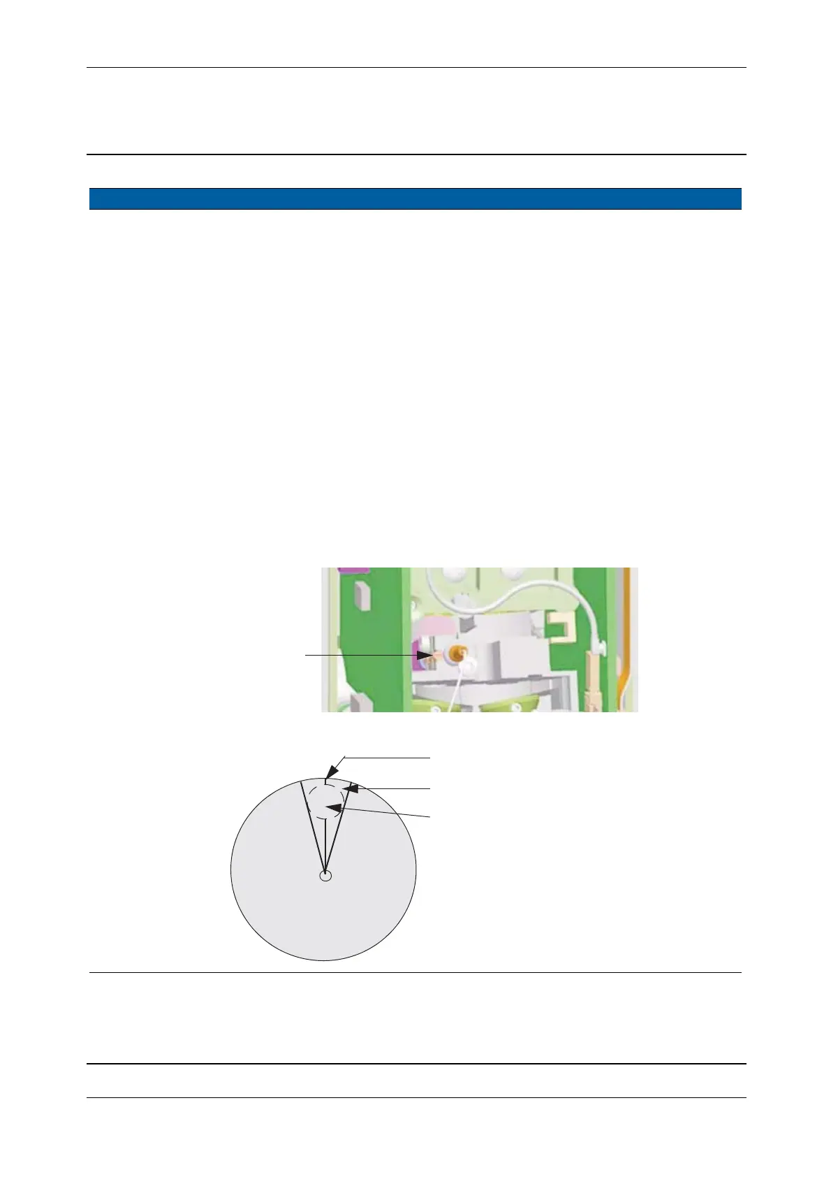
5 Remarks The reference greywedge has a “0” position where the area of highest
density jumps to the area of lowest density Fig. 6-78.
The reference greywedge must not be positioned in this high-low
transition area. The adjustment will be very unstable, the wrong
position is characterised by the running bar is reacting much more
sensitive.
The proper adjustment position will allow a larger turn.
Fig. 6-77 Reference greywedge adjustment
Fig. 6-78 Reference greywedge disc
Item Performance Description Result Notes
greywedge
Reference
A
Forbidden range
high
low
density
density
“0” position
Path of the reference light