Chapter 6
Adjustment and verification
Trimble S, VX, SPS & RTS Service Manual6 - 108 P/N 57150002, Revision 5.0
F
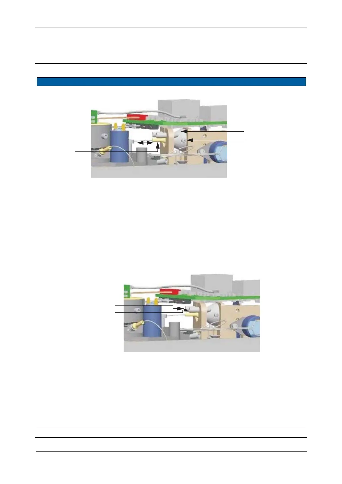
Fig. 6-121 Receiver fibre focus to APD
5 Align receiver fibre
position to APD.
A. Turn one screw to
maximize the signal
ratio (ext/int), see Fig.
6-119 on page 6-106 .
B. Turn the other screw to
maximize the signal
ratio (ext/int).
C. Turn the first screw
again.
D. Lock alignment screws
with Glue MS 1855.
Note – Find the
maximum signal
only!
Tolerances is
used when
adjusting the
reference
signal.
Fig. 6-122 Receiver fibre alignment to APD
6 Position receiver fibre
and receiver fibre
bender.
A. Position fibre bender in
line with the EDM
frame.
B. Position receiver fibre
underneath the black
pad.
C. Make sure the receiver
fibre is not bending
less than a radius of 15
mm.
Item Performance Description Result Notes
B&D
Receiver
C
locking screw
Focus
E
A&C
B
Alignment