Chapter 6
Adjustment and verification
Trimble S, VX, SPS & RTS Service Manual6 - 144 P/N 57150002, Revision 5.0
F
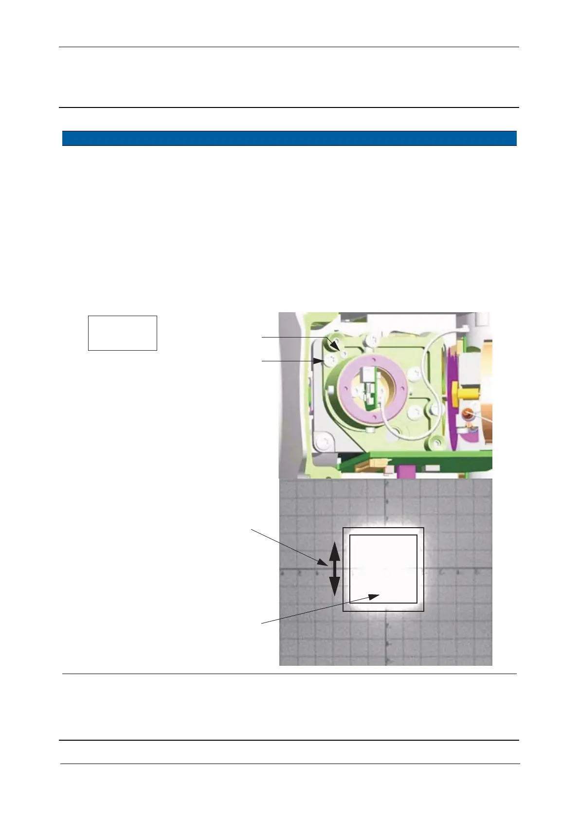
9 Adjust vertical
position.
A. Loosen the clamp
screw.
B. Adjust vertical position
by turning the
adjustment screw, see
Fig. 6-156 on page 6-
144 .
C. Tighten the clamp
screw using a torque
wrench.
3 Ncm. The locking screw
has to touch the
ground (frame) so
that there is no
vertical play. Avoid
any pressure by the
locking screw.
Use one Torx T8
screw driver (B) and
one 1,3 mm allen key
(A).
Fig. 6-156 Vertical alignment of tracker transmitter
Item Performance Description Result Notes
B - Adjustment screw
A - Clamp screw
Arrow shows direction when turning
the vertical adjustment screws
For opposite movement of beam
turn the adjustment screws
Tracker transmitter spot
3Ncm/
0.27 lbfin
the opposite way
Tolerance frame shows situation
with 1,2m distance