6. EM GUI orientation
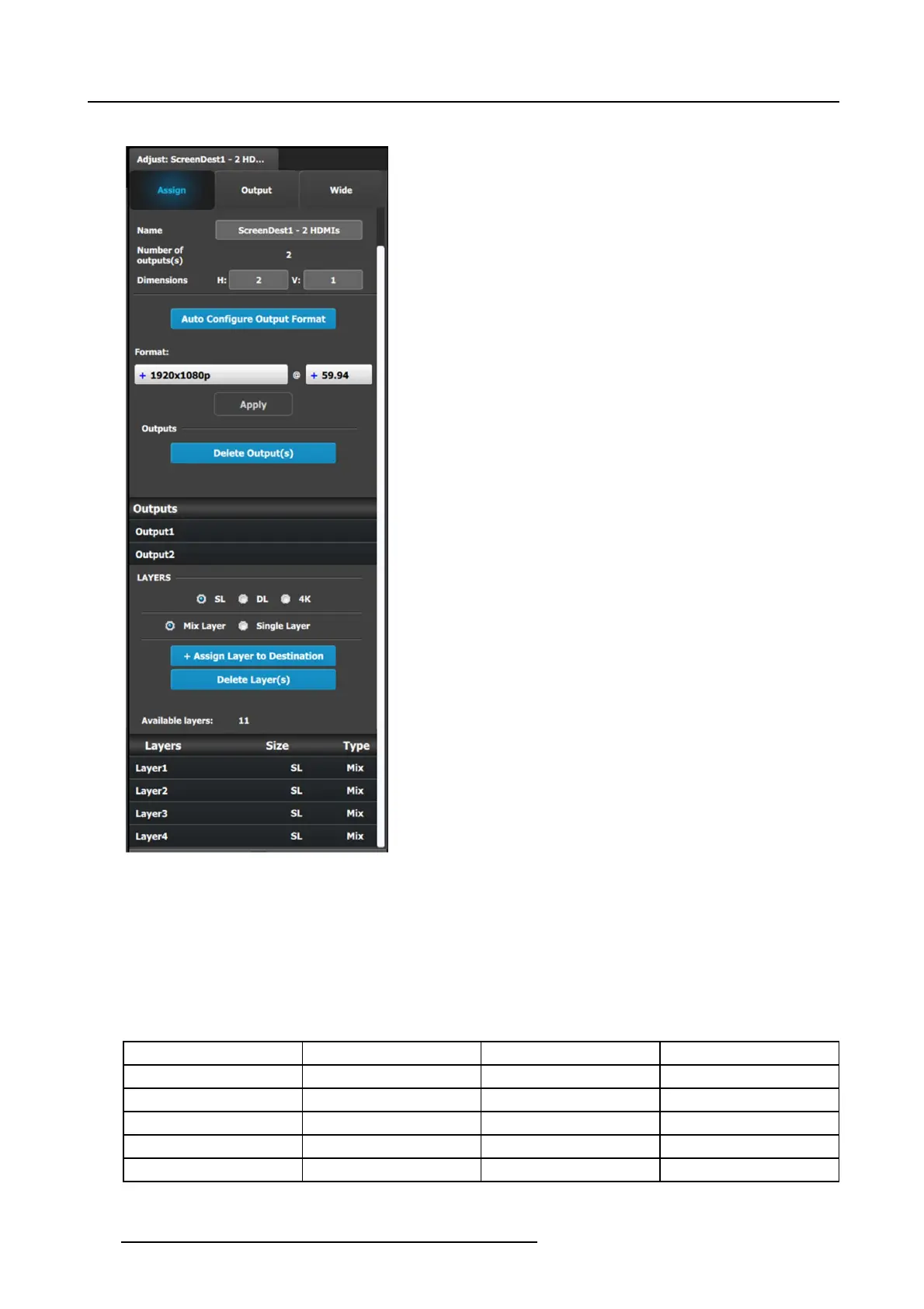
Assign Menu
• Name: A djusts the name of the Destination.
• Destination type: Reports the type of destination Screen
or Aux. Can co nvert from Screen to Aux if it meets
requirements.
• Number of output(s): Reports the nu mber o f output
configurations in the destination.
• Dimension: Adjust the output confi guration layout .
• Auto con figure Output format: Reads the EDID information
of the connected device to acquire its format. If more than
one device is connected to the destination, it reads the
format of the first output. This feature is not available for
SDI outputs.
• Output(s) format: Adjusts the output format of the
destination. This is a pplied to all outputs t hat are added into
this destination.
If you cannot find the output format in the list, it is possible
that the connector capacity for the connector is too small.
Remove the outputs from the D estination; update the con-
nector capacity; and check again. (Refer to "Configuration
Menu > Adjustme nt > Output Configuration", page 118, and
see the subsections "H ow to delete Output" and "Output ad-
justment panel > Connector Menu.")
• Outputs: Provides a list of the output configurations
assigned to the Destination.
For Aux destinations, only 1 Output configuration is shown
orisallowedtobedefined. From this menu ou tputs can be
deleted or added as in the output configuration m enu.
• Layer (only applicable when Destination is a Screen). You
can assign a size to the Layer: SL (2K Single Link), DL
(Dual Link), or 4K. Yo u can a lso ma ke the Layer either a
Mixing Layer or a Single La yer.
The list s hows the Layers assigned to this Destination.
A word about layers
Adding to the general description above about layers, mores specifically a E MP ´s Screen Destination has 1 fixed Mixing layer, its
BG. Then there ar e a number of mixing layers available in the system.
The E2 has 2 Banks of 8 Mixing Layers for a total of 16 Mixing Layers or 32 Single Layers (32L). Thes e 16 Mixing Layers can be
assigned to Destinations, using up to 4 O utputs (1 B ank). If a D estination uses Outputs from both Banks, the Mixing Layer c ount is
reduced to 8. An E2 Jr. ha
s a single Bank of 8 Mixing Layers for a total of 8 Mixing Layers or 16 Single La yers (16L).
An S3–4k has 1 bank of 4 M ixing Layers for a total of 4 Mixing Layers or 8 Single Layers (8L). These 8 Mixing Layers can be assigned
to Destinations, us ing up to 4 Outputs (1 Bank). A n S3–4k Jr. has a single Bank of 2 Mixing Lay ers for a total of 2 Mixing Lay ers or
4 S ingle Layers (4 L).
Processor Banks Mixing Layers Single Layers
E2 2 16 32
E2 Jr. 1 8 16
S3–4K 1 4 8
S3–4K Jr. 1 2 4
EX NA NA NA
130 R5905948 EVENT MASTER DEVICES 17/07/2017